Electro-optic sampling method based on polarization rotation effect of electroabsorption modulator

An electro-absorption modulator and electro-optical sampling technology, which is applied in the field of optoelectronics, can solve the problems of high driving current, low sampling rate, and long carrier life, and achieve short life, high-speed working rate, and high modulation sensitivity. Effect

Inactive Publication Date: 2011-03-30
UNIV OF ELECTRONICS SCI & TECH OF CHINA
View PDF0 Cites 0 Cited by
  • Summary
  • Abstract
  • Description
  • Claims
  • Application Information

AI Technical Summary

Problems solved by technology

The electro-optic sampling method based on the semiconductor optical amplifier (SOA) is used to solve the shortcomings of the previous electro-optic sampling that cannot be integrated, but it requires a higher drive current
In addition, semiconductor optical amplifiers have the characteristics of long carrier life, which restricts the sampling rate, and the sampling rate that can be achieved is not very high.

Method used


Image

  • Electro-optic sampling method based on polarization rotation effect of electroabsorption modulator
  • Electro-optic sampling method based on polarization rotation effect of electroabsorption modulator
  • Electro-optic sampling method based on polarization rotation effect of electroabsorption modulator

Examples


Embodiment Construction

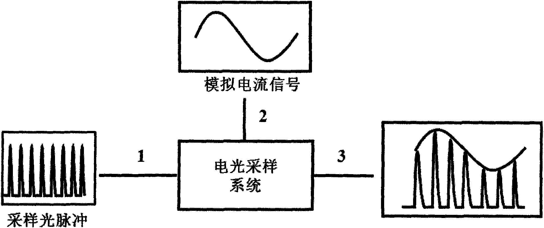
[0036] through the pair such as image 3 An example of the electro-optic sampling device system shown is simulated and numerically simulated to verify the electro-optic sampling method based on the polarization rotation effect of the electro-absorption modulator proposed by the present invention.

[0037] Step 1 Composition of electro-optic sampling system

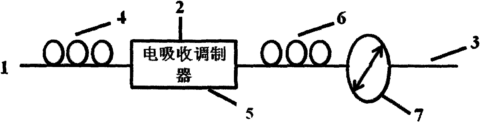
[0038] like figure 2As shown, the electro-optical sampling system is composed of an input optical fiber 1, a first polarization controller 4, an electroabsorption modulator 5, a second polarization controller 6, a polarization beam combiner 7 and an output optical fiber 3 through optical connections in sequence;

[0039] Step 2 Determination of optical working parameters

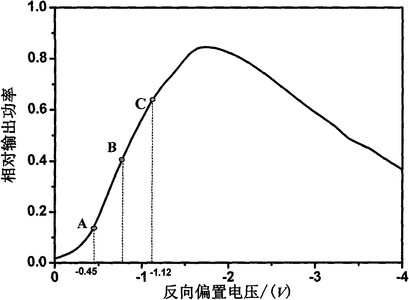
[0040] Step 2a: From the technical description document of the electroabsorption modulator 5, determine the minimum value 0 and the maximum value -4V of the input reverse voltage intensity of the electroabsorption modulator and the maximum allowable i...


PUM


Abstract

The invention provides an electro-optic sampling method based on the polarization rotation effect of an electroabsorption modulator. By adjusting the optical working parameter and the voltage working range of an electro-optic sampling system, the method utilizes the polarization rotation effect of the electroabsorption modulator to obtain the e1ectrooptic property that the output light power is linearly increased along with the voltage strength of an input signal; and the e1ectrooptic property is utilized to accomplish the linear modulation of the pulse strength of an input sampling light by signal voltage, so as to obtain the sample of the signal voltage. The method has the advantages of small volume, easy assembly, high modulation sensitivity and sampling rate, etc. The method greatly promotes the realization of real-time disturbance-free measurement of characteristics of the next generation of optical analog-to-digital converters and ultraspeed electronic devices.

Description

technical field [0001] The invention belongs to the field of optoelectronic technology, the field of integrated optics and the field of photoelectric signal processing, and particularly relates to an electro-optic sampling method based on an electro-absorption modulator. Background technique [0002] Electro-optic sampling is a photoelectric signal conversion technology, which utilizes the analog signal voltage to be sampled to modulate the sampled optical pulse signal through a certain electro-optical medium to obtain an optical pulse signal output whose intensity is linearly modulated, and realizes real-time acquisition of analog electrical information and Measurement. like figure 1 As shown, the optical input terminal 1 of the electro-optic sampling system inputs a sampling optical pulse with a high repetition rate and equal amplitude, and at the same time inputs the analog signal voltage to be sampled at the electrical input terminal 2, and the optical power can be obta...

Claims


Application Information

Patent Timeline
Patent Type & Authority Patents(China)
IPC IPC(8): G02F1/01
Inventor 刘永杨惠姣张谦述张尚剑徐天翔刘永智李和平
Owner UNIV OF ELECTRONICS SCI & TECH OF CHINA
Why Eureka
Try Eureka