Heat exchange device

A technology of heat exchange device and heat exchanger, which is applied to thermoelectric device components, thermoelectric devices that only use Peltier or Seebeck effect, etc., and can solve problems such as difficulty in fully releasing thermal stress and reduced reliability of thermal stress

Inactive Publication Date: 2009-09-23
YAMAHA CORP
View PDF2 Cites 4 Cited by
  • Summary
  • Abstract
  • Description
  • Claims
  • Application Information

AI Technical Summary

Problems solved by technology

This makes it difficult to sufficiently release the thermal stress from the thermoelectric element 58, whereby the reliability of the thermoelectric module 50a against thermal stress decreases.

Method used


Image

  • Heat exchange device
  • Heat exchange device
  • Heat exchange device

Examples


Embodiment Construction

[0024] The present invention will be described in further detail by way of example with reference to the accompanying drawings.

[0025] 1. The first embodiment

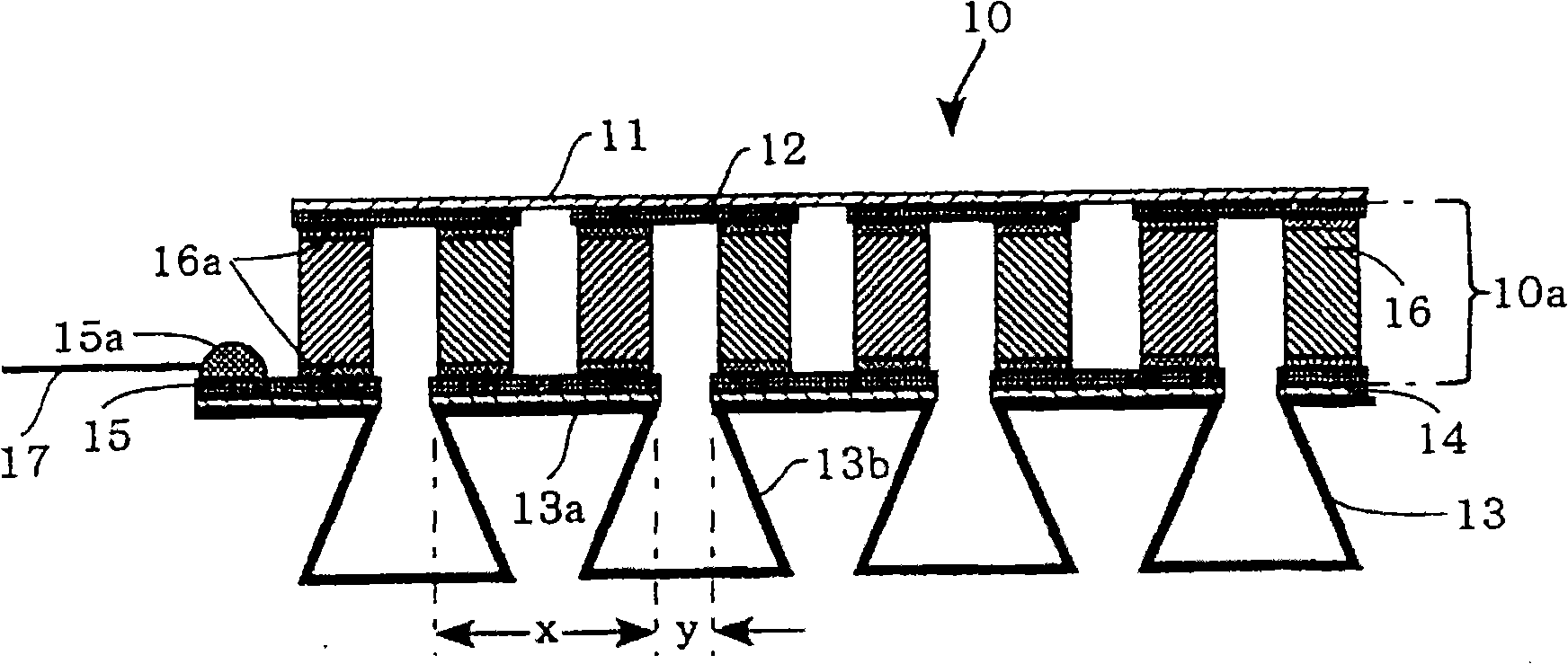
[0026] figure 1 is a cross-sectional view showing the configuration of the heat exchange device 10 according to the first embodiment of the present invention. The heat exchanging device 10 includes a substrate 11, a heat dissipating electrode 12 formed under the substrate 11, a plurality of corrugated fins 13 (commonly serving as a heat exchanger on the heat absorbing side), via a A permanent insulating resin layer 14 is connected to a heat absorbing electrode 15 on the upper surface of the corrugated fin 13, and a plurality of thermoelectric elements 16 electrically connected in series between the electrodes 12 and 15 via a solder layer (or metal) 16a.

[0027] A pair of terminals 15 a is formed on one end of the heat absorbing electrode 15 to establish electrical connection with the lead wire 17 . The thermoele...


PUM


Abstract

A heat exchange device includes a heat exchanger disposed in connection with at least one of a heat-dissipation electrode and a heat-absorption electrode, between which a plurality of thermoelectric elements is connected in series, via an insulating resin layer, which is composed of an epoxy resin or polyimide resin doped with fillers having high thermal conductivity, without intervention of a substrate. The heat exchanger corresponds to a plurality of corrugated fins which are constituted of a plurality of joint regions joining with one of the heat-dissipation electrode and heat-absorption electrode and a plurality of non-joint regions projecting externally from a plurality of gaps formed between the joint regions adjacently aligned together, wherein the joint regions and non-joint regions are alternately aligned. Thus, it is possible to achieve high reliability by reducing thermal resistance and thermal stress while increasing the maximum heat absorption coefficient (Qmax).

Description

technical field [0001] The invention relates to a heat exchange device comprising heat exchangers to which thermoelectric modules are connected in series between heat-dissipation electrodes and heat-absorption electrodes. thermoelectric elements. Background technique [0002] Conventionally known thermoelectric modules are designed such that different types of hotspot elements composed of P-type and N-type semiconductors are alternately arranged and connected in series between heat dissipating electrodes and heat absorbing electrodes via connecting metal such as solder. Various techniques have been developed to improve heat dissipation efficiency in thermoelectric modules, wherein a heat exchanger is for example coupled to a heat dissipating substrate or a heat absorbing substrate in order to form a heat exchange device. [0003] Various heat exchange devices have been developed and disclosed in various documents such as Patent Document 1. [0004] Patent Document 1: Japan...

Claims


Application Information

Patent Timeline
Patent Type & Authority Applications(China)
IPC IPC(8): H01L35/30H01L35/02
CPCH01L35/30H10N10/13
Inventor 堀尾裕磨
Owner YAMAHA CORP
Why Eureka
Try Eureka