
Band-pass filter device, method of manufacturing same, television tuner, and television receiver

A band-pass filter, electrode technology, used in television, discontinuous tuning with a separate pre-tuning circuit, color TV, etc., can solve the problems of complex manufacturing, increased manufacturing cost, and increased packaging cost, and achieve good filtering characteristics, noise reduction effect

Inactive Publication Date: 2009-09-23
SONY SEMICON SOLUTIONS CORP
View PDF2 Cites 3 Cited by
  • Summary
  • Abstract
  • Description
  • Claims
  • Application Information

AI Technical Summary

Problems solved by technology

Therefore, the manufacturing cost increases and the manufacturing becomes complicated
[0068] In addition, the hollow structure leads to an increase in the cost of forming the package, as in general MEMS (Micro-Electro-Mechanical Systems) devices

Method used


Image

  • Band-pass filter device, method of manufacturing same, television tuner, and television receiver
  • Band-pass filter device, method of manufacturing same, television tuner, and television receiver
  • Band-pass filter device, method of manufacturing same, television tuner, and television receiver

Examples


Embodiment Construction

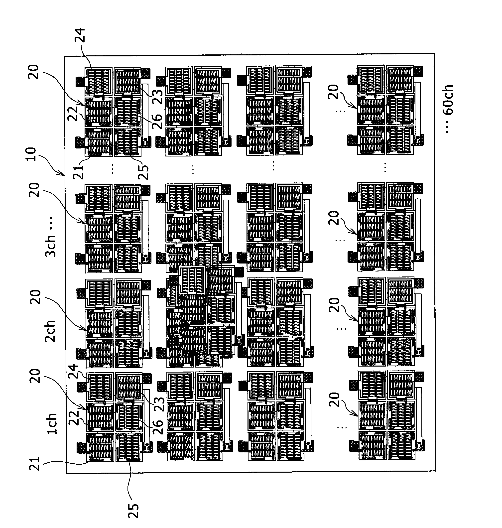
[0109] Next, we will refer to figure 1 The schematic floor plan depicts an embodiment of a bandpass filter arrangement according to the present invention.

[0110] Such as figure 1 As shown, the bandpass filter device 10 has a plurality of bandpass filter elements 20 on the main surface of the substrate 11 . The bandpass filter elements 20 respectively correspond to a plurality of frequency channels divided by frequency regions. For example, each bandpass filter element 20 is constituted by a plurality of piezoelectric resonators 21 to 26 . In the example shown in the drawing, for example, bandpass filter elements 20 are provided for 60 channels. Only part of the bandpass filter element 20 is shown in the figure.

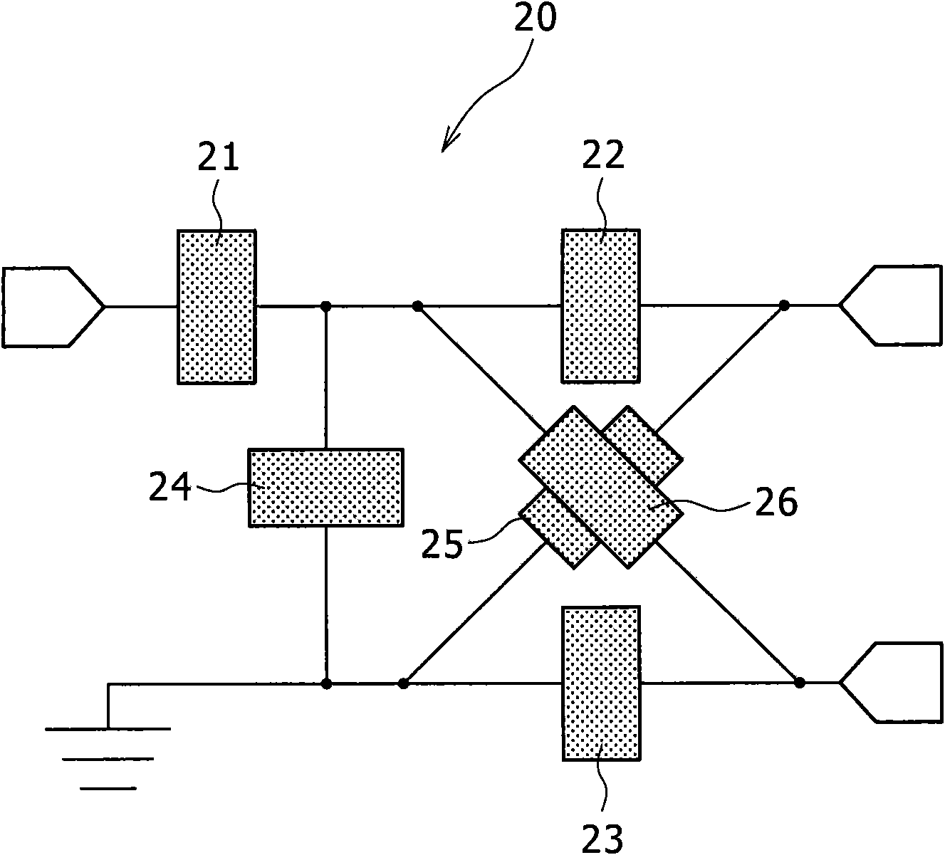
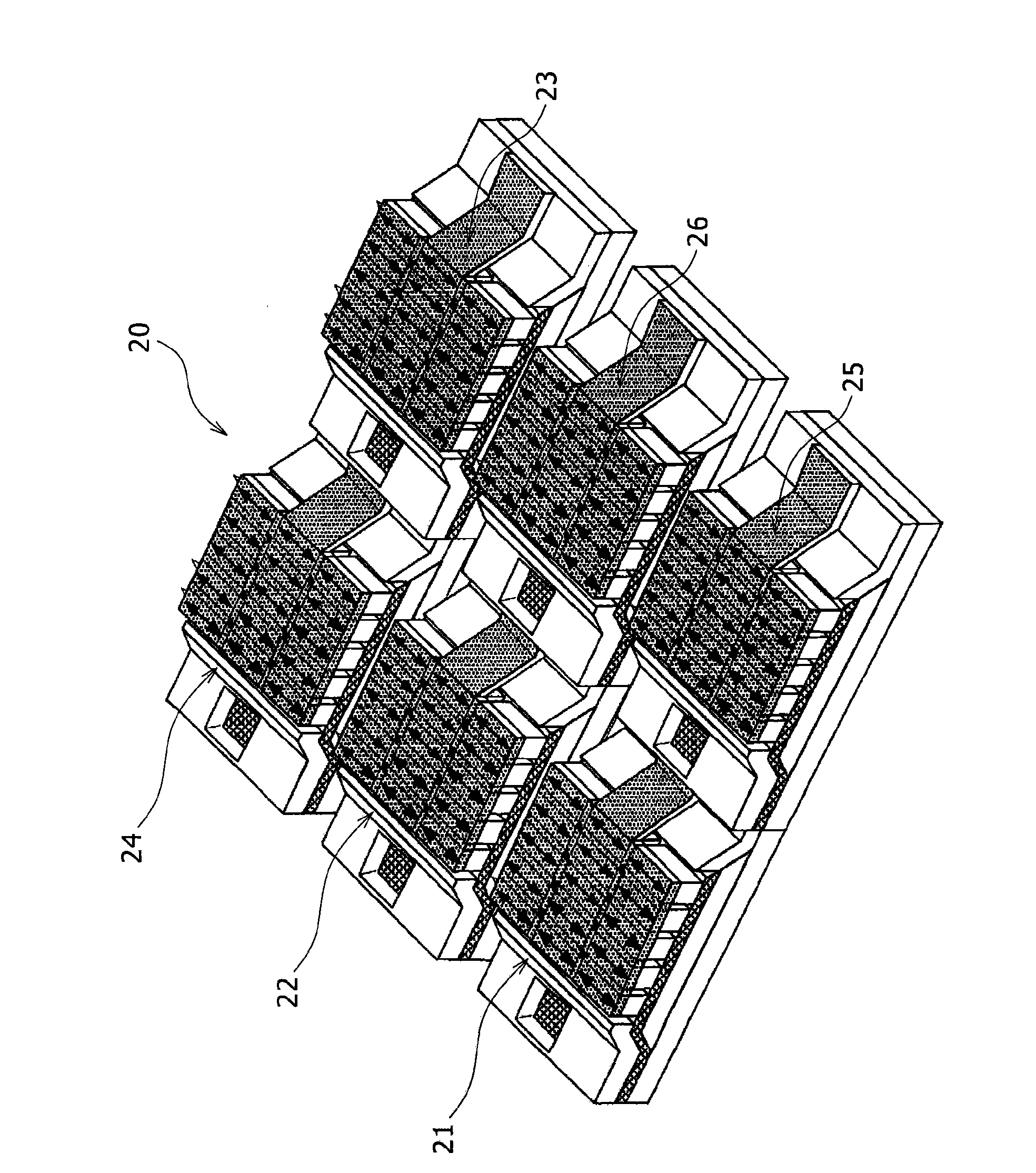
[0111] Next, we will refer to figure 2 circuit diagram, image 3 A schematic perspective view of and Figure 4 The structure of the bandpass filter element 20 is described in a schematic cross-sectional view of FIG.

[0112] Such as figure 2 with imag...


PUM

PropertyMeasurementUnit
lengthaaaaaaaaaa
thicknessaaaaaaaaaa
thicknessaaaaaaaaaa

Abstract

The invention discloses a band-pass filter device, a method of manufacturing same, a television tuner, and a television receiver. The band-pass filter device includes: a plurality of band-pass filter elements on a principal plane of a substrate; wherein the band-pass filter elements correspond to a plurality of respective channels divided by frequency regions, and each have a plurality of piezoelectric resonators. Each of the piezoelectric resonators includes a piezoelectric film whose periphery is supported by the substrate, a first electrode formed on a lower surface of the piezoelectric film, a second electrode formed on an upper surface of the piezoelectric film and formed in a state of overlapping at least a part of the first electrode with the piezoelectric film interposed between the second electrode and the first electrode, a lower space formed between the substrate and the piezoelectric film, and an upper space formed over the piezoelectric film. The invention has advantage of remarkably reducing noise of the receiving channel and executing high quality reception.

Description

[0001] Cross References to Related Applications [0002] The present invention contains subject matter related to Japanese Patent Application JP 2008-068965 filed in the Japan Patent Office on Mar. 18, 2008, the entire content of which is hereby incorporated by reference. technical field [0003] The present invention relates to a band-pass filter device and its manufacturing method, a TV tuner and a TV receiver. Background technique [0004] A system of a current television (hereinafter referred to as TV) channel tuner will be described below. [0005] As in a tuner of a high-quality terrestrial television receiver, a frequency selection filter method obtained by changing a coil (L) and a capacitor (C) as external parts is currently widely used for selecting a desired frequency from a wide frequency range. Channel method (especially in the case of a uniform bandwidth, the fractional bandwidth (%) varies greatly over a wide frequency band). [0006] Thus, a frequency selec...

Claims


Application Information

Patent Timeline
Patent Type & Authority Applications(China)
IPC IPC(8): H03H9/58H03H9/54H03H9/15H03J5/24H03H3/02H04N5/50H04N5/44H03H9/19H03H9/70
CPCH03H2003/0471H03H3/04H03H9/605H03H9/173H03H2003/0414H03H9/0095H03H9/564H03H9/703Y10T29/49005Y10T29/42
Inventor 吉田浩
Owner SONY SEMICON SOLUTIONS CORP
Learn More