Supercharge Your Innovation With Domain-Expert AI Agents!

Neon-light electronic transformer

A technology for electronic transformers and neon lights, applied in transformers, inductors, circuits, etc., can solve the problems of protection failure, troubled neon lights, and easy protection by mistake, and achieve the effect of improving operation stability, simplifying circuit structure, and eliminating potential safety hazards.

Inactive Publication Date: 2009-09-23
佛山市南海绰美儿童用品有限公司 +1
View PDF0 Cites 3 Cited by
  • Summary
  • Abstract
  • Description
  • Claims
  • Application Information

AI Technical Summary

Problems solved by technology

Due to the large discreteness of electronic components, it is difficult to adjust the sensitivity of the protection circuit to be consistent. If the sensitivity is too high, it is easy to miss the protection, and if the sensitivity is too low, the protection will fail. This is a technical problem that has plagued neon lighting technology for a long time.
In addition, in order to prevent high-voltage breakdown of the output winding N2, it must be made into two sets of layer-wound coils working in series. Generally, the design is about 2800 turns. Because the number of turns is too small and the high voltage is insufficient, the number of turns is too large and is limited by the space of the magnetic core. , which limits the further development of neon electronic transformer technology

Method used


Image

  • Neon-light electronic transformer
  • Neon-light electronic transformer
  • Neon-light electronic transformer

Examples


Embodiment Construction

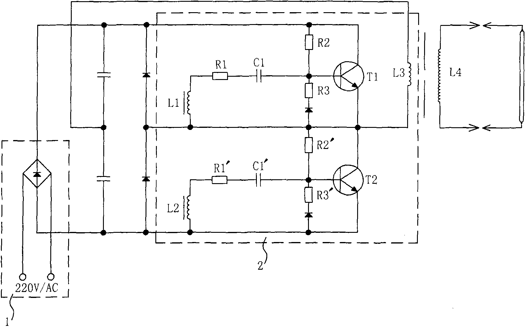
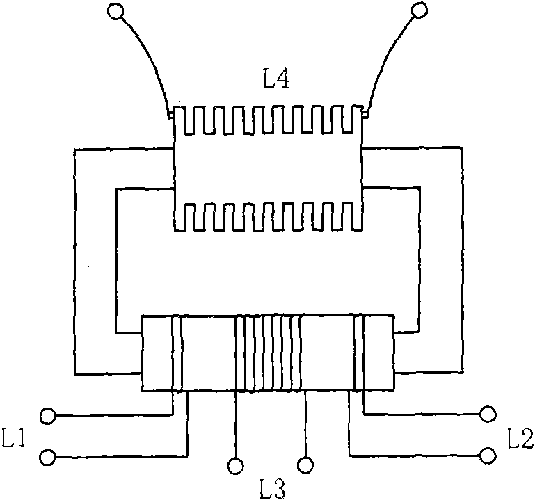
[0012] refer to figure 1 , figure 2 As shown, the neon electronic transformer of the present invention includes a power input circuit 1, a self-excited oscillation circuit 2 and an output coil L4, and the self-excited oscillation circuit 2 includes bias current resistors R2, R2', feedback coils L1, L2, secondary coils L3, Capacitors C1, C1', current-limiting resistors R1, R1', feedback coils L1, L2, secondary coil L3, output coil L4 are wound on the same magnetic core, feedback coils L1, L2 have 2 to 4 turns optional, secondary The primary coil L3 is selected between 90 and 100 turns; one end of the bias current resistor R2, R2' is respectively connected to the collectors of the two triodes T1, T2, and the other end is respectively connected to the feedback capacitor C1 and the coil L1, the capacitor C1' and the feedback coil L2 The formed series circuit is connected in parallel to the bases of transistors T1 and T2, and the current-limiting resistors R1 and R1' are respect...


PUM

PropertyMeasurementUnit
Number of turnsaaaaaaaaaa
Resistanceaaaaaaaaaa

Abstract

The invention discloses a neon-light electronic transformer belonging to the technical field of electronic transformers. The neon-light electronic transformer is technologically characterized by comprising a power supply input circuit, a self-oscillation oscillation circuit and an output coil L4, wherein the self-oscillation oscillation circuit comprises current bias resistors R2 and R2', feedback coils L1 and L2, a secondary coil L3, capacitors C1 and C1' and current-limiting resistors R1 and R1', wherein the feedback coils L1 and L2, the secondary coil L3 and the output coil L4 are wound onthe same magnetic core; one end of the current bias resistor R2 and one end of the current bias resistor R2' are respectively connected with collectors of two triodes T1 and T2, and the other end of the current bias resistor R2 and the other end of the current bias resistor R2' are respectively connected in parallel with a series circuit formed by the feedback capacitor C1, the feedback coil L1, the capacitor C1' and the feedback coil L2 are connected with bases of the triodes T1 and T2; and the current-limiting resistors R1 and R1' are respectively connected in series between the feedback coil L1 and the feedback capacity C1 and between the feedback coil L2 and the capacitor C1'. The neon-light electronic transformer is characterized in that the output coil L4 has a turn number from 3200 turns to 6500 turns, the capacitors C1 and C1' have the capacity of 0.33 microfarad to 2.2 microfarad, and the current-limiting resistors R1 and R1' have the resistance values of 1 ohm to 4.7 ohms. The invention has the advantages of simple structure, safety, reliability and long service life and is used for neon-light illumination and power supply.

Description

technical field [0001] The present invention relates to an electronic transformer, more specifically, it relates to a neon lamp electronic transformer. Background technique [0002] At present, the neon electronic transformers with AC output are generally divided according to the length of the load tube: 1 to 4 meters for low power; 4 to 8 meters for medium power; more than 8 meters for high power. Because low-power is mostly used for scanning, high-power AC induction is too large, and creepage and fire are likely to occur, so the market sales of medium-power neon lights are the largest. The circuit structure of the existing neon lamp electronic transformer is as follows: image 3 , Figure 4 As shown, B1 in the figure is used for self-excited oscillation, and B2 is used for power output. Since the winding L5 in B1 and the winding N1 in B2 work in series, when the load connected to the output winding N2 is damaged and opened, positive feedback will be formed in B1 and the ...

Claims


Application Information

Patent Timeline
IPC IPC(8): H05B41/24H01F38/10
Inventor 欧应成蒋华安
Owner 佛山市南海绰美儿童用品有限公司
Features
  • R&D
  • Intellectual Property
  • Life Sciences
  • Materials
  • Tech Scout
  • Unparalleled Data Quality
  • Higher Quality Content
  • 60% Fewer Hallucinations
Learn More