High cavitation, low tonnage rubber mold machine and method

A technology for injection molds and injection molds, which is applied in the direction of forming pressure heads, etc., and can solve problems such as loss and processing time

Inactive Publication Date: 2009-09-23
FEDERAL MOGUL CORP
View PDF0 Cites 1 Cited by
  • Summary
  • Abstract
  • Description
  • Claims
  • Application Information

AI Technical Summary

Problems solved by technology

Even quick die changes take up valuable machining time when going from one step of die change to the next and when the process cannot be conveniently automated
Therefore, lost time during mold changes is a serious problem in the field of injection molding

Method used


Image

  • High cavitation, low tonnage rubber mold machine and method
  • High cavitation, low tonnage rubber mold machine and method
  • High cavitation, low tonnage rubber mold machine and method

Examples


Embodiment Construction

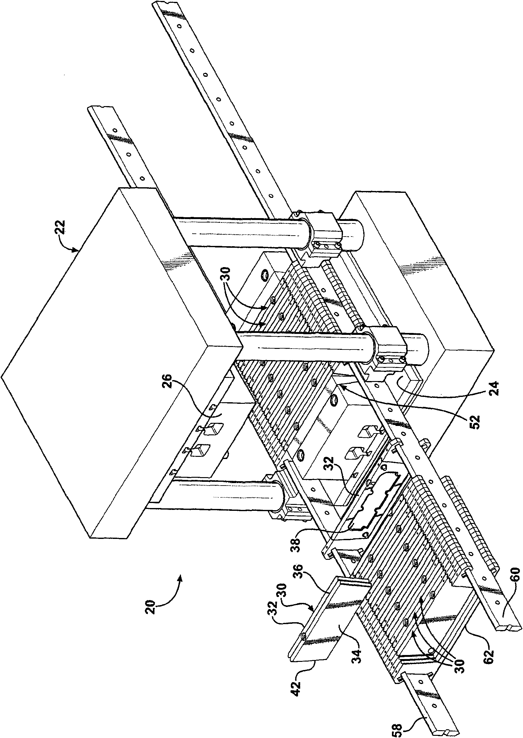
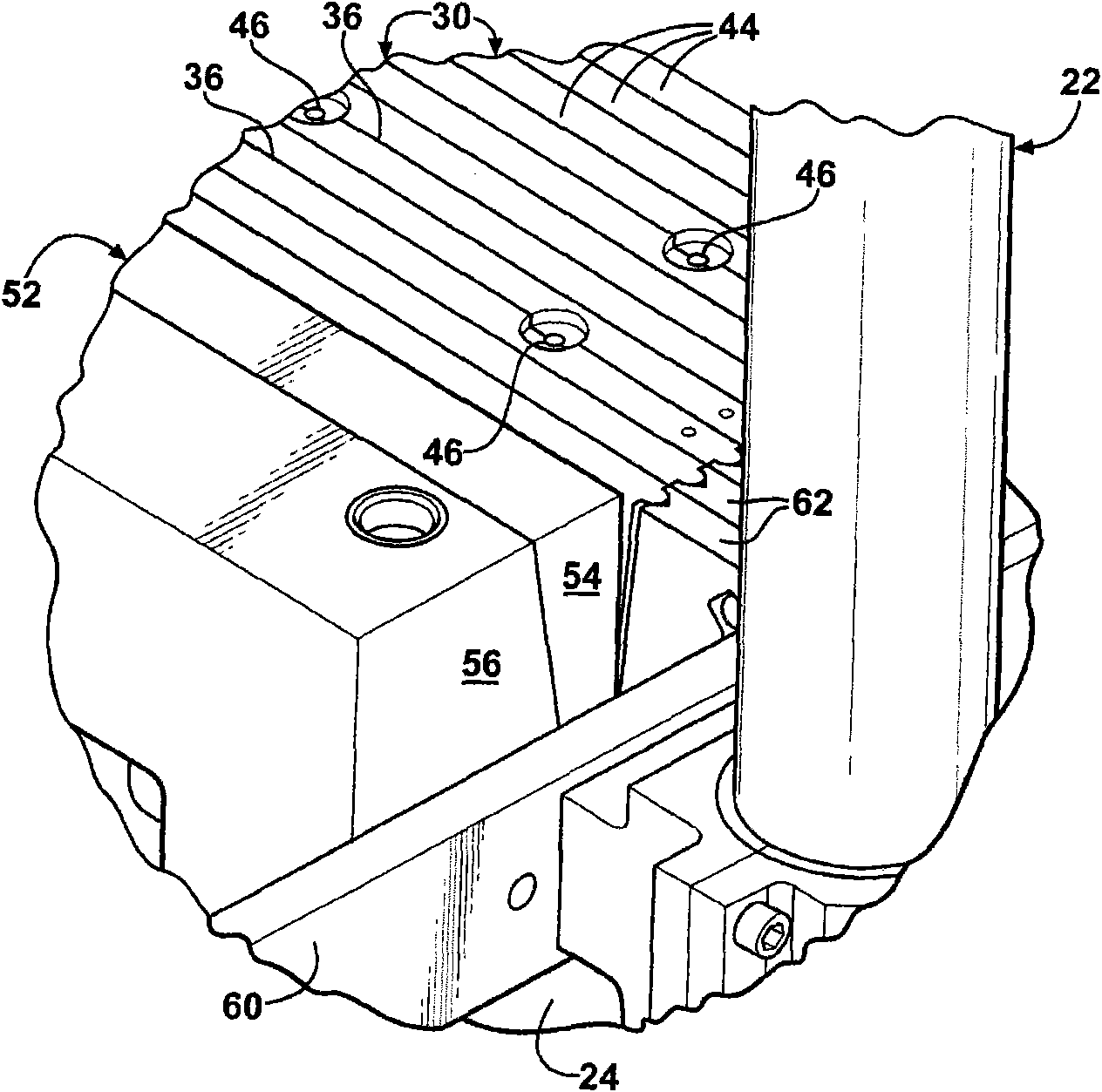
[0020] As shown in the drawings, wherein in all the drawings, the same numerals represent the same or corresponding components, a rubber injection molding apparatus for simultaneously molding multiple workpieces in separate molds by a single press is shown at 20 Show. A rubber injection molding press, generally indicated at 22, includes a press bed 24 and a vertically oriented press slide 26 which supports reciprocating motion on a vertical path toward and away from a press bed 24. The press slide 26 can be equipped with multiple heaters, runner system 28 and nozzles, as shown in Figures 6 and 7, to distribute the molten rubber to multiple molds at the appropriate time in the molding cycle.

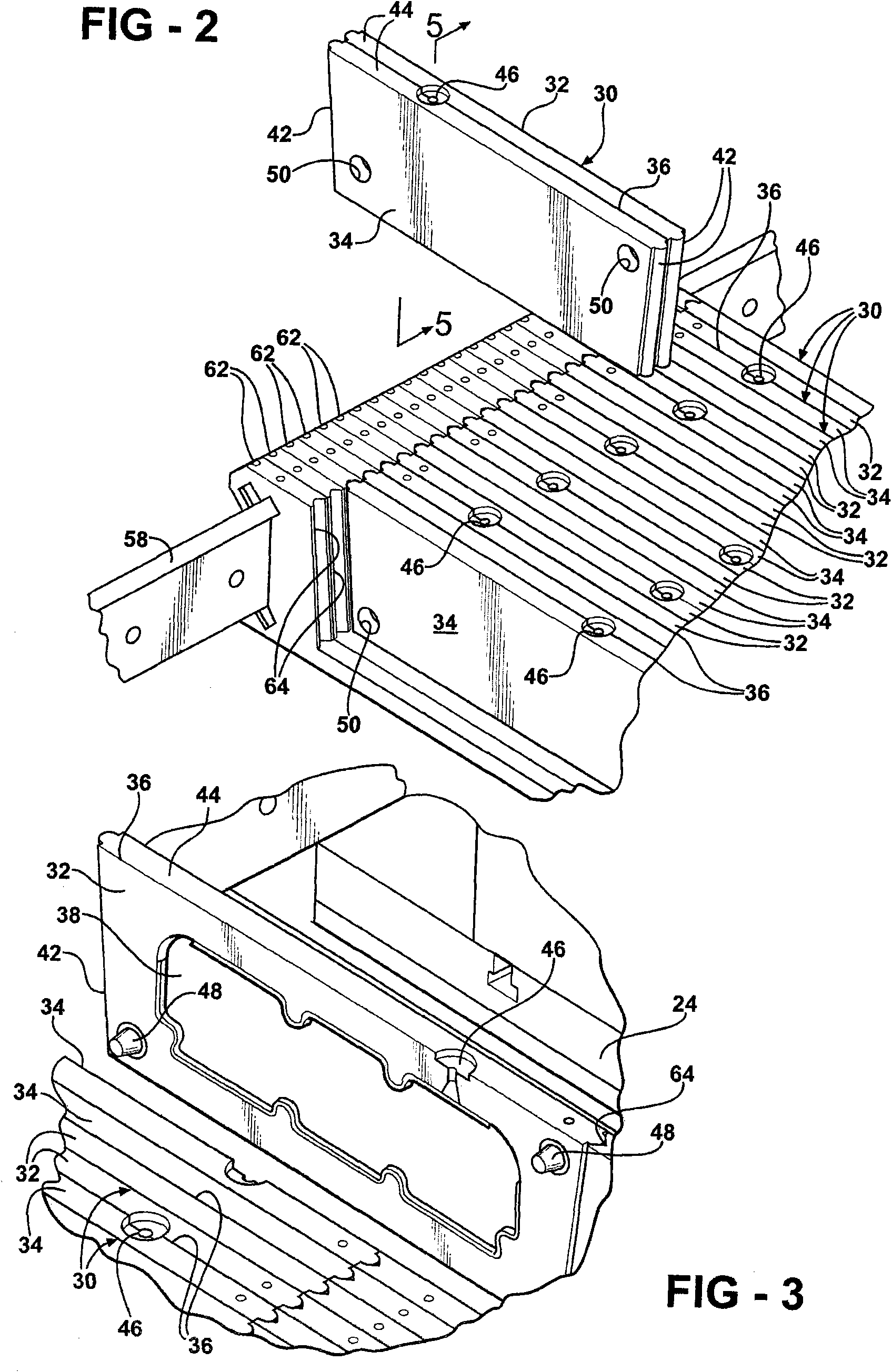
[0021] A plurality of separate and independent injection molds, generally indicated at 30, are distributed within the pressure zone, for example, between the press 24 and the press slide 26, or as described alternatively, between the Within the path of the reciprocating motion of the pre...


PUM


Abstract

A rubber injection molding apparatus and method for simultaneously molding a plurality of work parts (40) in separate molds (30) using a single, vertically oriented press machine (22). A clamping mechanism (52) is responsive to the vertical, reciprocating motion of the press ram (26) for converting the generally vertical motion of the press ram (26) into a horizontal clamping force to squeeze and hold the molds while rubber is injected into their cavities (38). The molds (30) each have two mold halves (32, 34) joining one another along a parting line interface (36) with the mold cavity (38) in between. The mold halves (32, 34) are received in universal carriers (62), which in turn are suspended between and slideable along spaced - apart first (58) and second (60) rails. A large number of mold cavities (38) can be filled simultaneously using a vertically oriented press machine (22). The plurality of molds (30) may contain different part configurations which are filled simultaneously in a single molting operation. Because the molds (30) are not fastened to platens as in prior art vertical press machines, changeover times are substantially decreased.

Description

technical field [0001] The present invention relates to a rubber injection molding device and method for simultaneous injection molding of multiple workpieces in separate horizontally arranged molds using an independent vertically oriented press. Background technique [0002] One of the most common methods of molding rubber resin into workpieces is through a process called injection molding. Injection molding is accomplished by an injection molding machine, which is usually a large piece of industrial fixture. According to the injection molding process, rubber resin is fed into a hopper where various colorants and other properties can be introduced. A barrel or other device receives the resin and raises its temperature to a suitable melting point. Once molten, the resin is injected into a mold cavity. [0003] Due to the extreme pressures generated during injection molding, the two mold halves must be firmly supported against each other in a high tonnage press. Presses u...

Claims


Application Information

Patent Timeline
Patent Type & Authority Applications(China)
IPC IPC(8): B28B3/06
CPCB29C45/64B29C45/2673
Inventor 加里·L·格罗思
Owner FEDERAL MOGUL CORP
Why Eureka
Try Eureka