Universal combined type die forging tool

A combined and versatile technology, applied in the direction of forging/pressing/hammer devices, manufacturing tools, metal processing equipment, etc., can solve the problem of low microstructure and mechanical properties, restricting the development of precision die forging technology, and poor surface quality of products, etc. problems, to achieve low maintenance costs, accurate positioning and guidance, and long service life

Inactive Publication Date: 2019-02-19
JIANGLU MACHINERY & ELECTRONICS GROUP
View PDF7 Cites 2 Cited by
  • Summary
  • Abstract
  • Description
  • Claims
  • Application Information

AI Technical Summary

Problems solved by technology

There are also some companies in the weapon industry and aerospace industry that use precision die forging technology to produce forging blanks, and have achieved good economic benefits. However, compared with the automotive industry, the scale is generally small, mainly due to the variety of products, small batches, and high mold production costs. Objective factors such as poor mold interchangeability and inconvenient loading and unloading of molds restrict the application of forgings on presses.
Therefore, in the process of processing and manufacturing, free forging or ordinary die forging technology is usually used. Compared with precision die forging, the microstructure and mechanical properties of forgings are lower, the machining allowance is large, the processing efficiency is low, the material utilization rate is low, and the manufacturing cost High, poor product surface quality
[0003] With the development requirements of lean production and green manufacturing, precision die forging technology has been developed. In addition to the tonnage limitation of the equipment itself, the mold cost and the traditional mold design method make only forgings with a small range of sizes suitable for a certain equipment, and equipment investment is also restricted. The development of precision die forging technology
[0004] Therefore, the traditional mold design method cannot be adopted, and problems such as mold production, maintenance cost, mold versatility, quick mold loading and unloading, and product size coverage must be solved

Method used


Image

  • Universal combined type die forging tool
  • Universal combined type die forging tool
  • Universal combined type die forging tool

Examples


Embodiment Construction

[0036] In order to enable those skilled in the art to better understand the technical solution of the present invention, the present invention will be described in detail below in conjunction with the accompanying drawings. The description in this part is only exemplary and explanatory, and should not have any limiting effect on the protection scope of the present invention. .

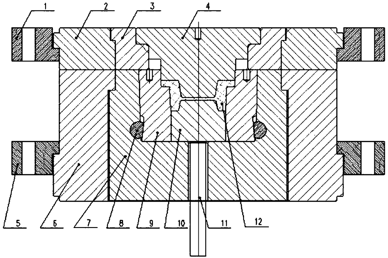
[0037] Such as Figure 1-Figure 12 Shown, the concrete structure of the present invention is: it is made up of upper pressure ring 1, upper die cover 2, upper transition cover 3, upper die core 4, lower pressure ring 5, lower die cover 6, lower transition cover 7, lower die 9. The lower mold core 10, the ejector rod 11, etc.; the upper mold sleeve 2 and the lower mold sleeve 6 are respectively matched with the upper transition sleeve 3 and the lower transition sleeve 7, and the upper mold sleeve 2 and the lower mold sleeve 6 are used for the upper transition The positioning and fixing of the sleeve 3 ...


PUM


Abstract

The invention discloses a universal combined type die forging tool. The universal combined type die forging tool is composed of an upper press ring, an upper die sleeve, an upper transition sleeve, anupper die core, a lower press ring, a lower die sleeve, a lower transition sleeve, a lower die, a lower die core, an ejector rod and the like. The upper die sleeve is matched with the upper transition sleeve, the lower die sleeve is matched with the lower transition sleeve, the upper die sleeve and the lower die sleeve are used for positioning and fixing the upper transition sleeve and the lowertransition sleeve separately, the upper transition sleeve and the lower transition sleeve are used for positioning and fixing the upper die core and the lower die, a fastening pin is used for fastening and positioning the lower die, and the ejector rod ejects a formed forge piece out of a lower die cavity. The universal combined type die forging tool can be used for producing all parts below the production extreme dimension of a certain type of forging device and can well control the die manufacturing cost, and meanwhile has the characteristics of being convenient to mount and dismount, low inmaintenance cost, long in service life, good in interchangeability and the like.

Description

technical field [0001] The invention belongs to the field of hot forging tooling, in particular to a universal combined die forging tooling. Background technique [0002] The degree of die forging in the automobile industry is relatively high. For example, the planetary gears, sun gears, and differentials of automobiles are all produced by precision die forging, which is at the forefront of forging applications in China. There are also some companies in the weapon industry and aerospace industry that use precision die forging technology to produce forging blanks, and have achieved good economic benefits. However, compared with the automotive industry, the scale is generally small, mainly due to the variety of products, small batches, and high mold production costs. Objective factors such as poor mold interchangeability and inconvenient loading and unloading of molds restrict the application of forgings on presses. Therefore, in the process of processing and manufacturing, f...

Claims


Application Information

Patent Timeline
Patent Type & Authority Applications(China)
IPC IPC(8): B21J13/02B21J13/14B21J13/03
CPCB21J13/02B21J13/03B21J13/14
Inventor 彭长贵莫竞芳宋海锋黄林春蒋秋娥王倩朱旭吴丹杨秀娟陈跃进
Owner JIANGLU MACHINERY & ELECTRONICS GROUP
Why Eureka
Try Eureka