Oil well pipe for expansion in well and two-phase stainless steel for use as oil well pipe for expansion

A technology of duplex stainless steel and oil well pipe, applied in the field of duplex stainless steel, can solve problems such as uneven deformation

Inactive Publication Date: 2009-09-23
SUMITOMO METAL IND LTD
View PDF2 Cites 7 Cited by
  • Summary
  • Abstract
  • Description
  • Claims
  • Application Information

AI Technical Summary

Problems solved by technology

Therefore, the above-mentioned bell-shaped portion may deform unevenly

Method used


Image

  • Oil well pipe for expansion in well and two-phase stainless steel for use as oil well pipe for expansion
  • Oil well pipe for expansion in well and two-phase stainless steel for use as oil well pipe for expansion

Examples


Embodiment 1

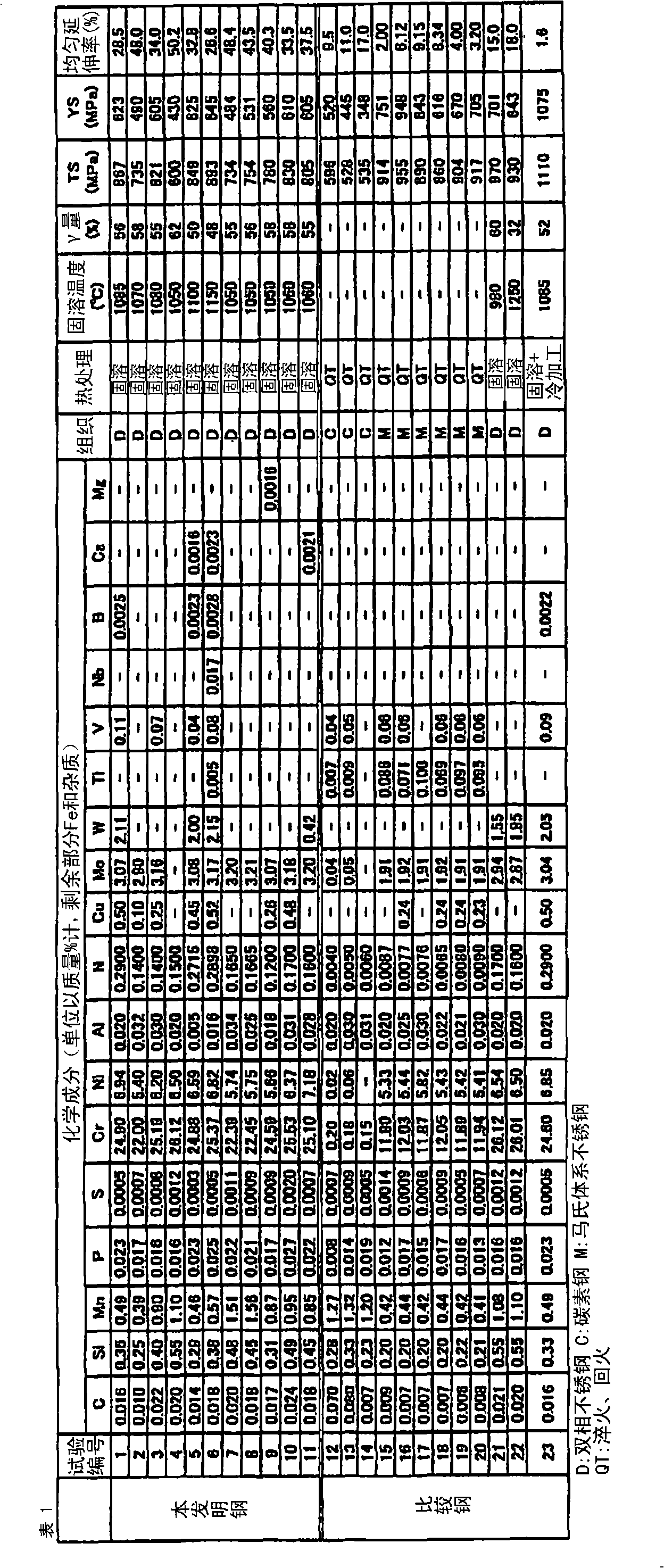
[0068] A plurality of steels having the chemical compositions shown in Table 1 were melted to produce billets. Hot forging and hot rolling were performed on the produced billets to form a plurality of test steel plates having a thickness of 30 mm, a width of 120 mm, and a length of 300 mm.

[0069] Table 1

[0070]

[0071] The "Organization" column in Table 1 indicates the steel type of each test number. "D" means duplex stainless steel, "C" means carbon steel. "M" indicates martensitic stainless steel. Referring to Table 1, test numbers 1 to 11 and 21 to 23 are duplex stainless steels. Numbers 12 to 14 are carbon steels, and test numbers 15 to 20 are martensitic stainless steels.

[0072] The steel plates of test numbers 1 to 23 were subjected to the heat treatment and cold working described in the "heat treatment" column in Table 1. Specifically, the steel sheets of test numbers 1 to 11 were subjected to solution treatment in a temperature range of 1050° C. to 1150°...


PUM

PropertyMeasurementUnit
yield strengthaaaaaaaaaa

Abstract

An oil well pipe for expansion which is expanded in a well. The oil well pipe is made of a two-phase stainless steel which has a chemical composition containing, in terms of mass%, 0.005-0.03% carbon, 0.1-1.0% silicon, 0.2-2.0% manganese, up to 0.04% phosphorus, up to 0.015% sulfur, 18.0-27.0% chromium, 4.0-9.0% nickel, up to 0.040% aluminum, and 0.05-0.40% nitrogen, with the remainder being iron and impurities, and has a structure having an austenite content of 40-90%. The oil well pipe for expansion has a yield strength of 276-655 MPa and a uniform elongation more than 20%. The oil well pipe has excellent expansibility.

Description

technical field [0001] The present invention relates to an oil well pipe and a duplex stainless steel, and more specifically, to an oil well pipe for diameter expansion that is expanded in a mine and a duplex stainless steel used for the oil well pipe for diameter expansion. Background technique [0002] When excavating wells (oil wells and gas wells) for the production of oil and gas, generally a plurality of oil well pipes called casings (casing) are inserted into the mine excavated by the drill pipe (drillpipe) to prevent damage to the mine wall. collapse. Conventional well construction methods are as follows. At the beginning, when the drill pipe is used to excavate the mine to a specified distance, the first casing is inserted. Next, when the mine is further excavated for a predetermined distance, a second bushing having an outer diameter smaller than the inner diameter of the first bushing is inserted. Thus, in the conventional construction method, the outer diamete...

Claims


Application Information

Patent Timeline
Patent Type & Authority Applications(China)
IPC IPC(8): C22C38/00C22C38/58C21D8/10
CPCC22C38/46C22C38/42C22C38/02C22C38/004C22C38/04C22C38/58C22C38/40C22C38/001C22C38/44
Inventor 高部秀树植田昌克近藤邦夫大江太郎
Owner SUMITOMO METAL IND LTD
Why Eureka
Try Eureka