Controller of variable valve actuator
A control device and valve mechanism technology, applied in the direction of engine control, valve device, engine components, etc., can solve the problems of friction torque increase, cost increase, etc., to reduce rated power, reduce power consumption, and prevent power consumption and the effect of an increase in rated power
- Summary
- Abstract
- Description
- Claims
- Application Information
AI Technical Summary
Problems solved by technology
Method used
Image
Examples
Embodiment approach 1
[0090] Structure of variable valve train
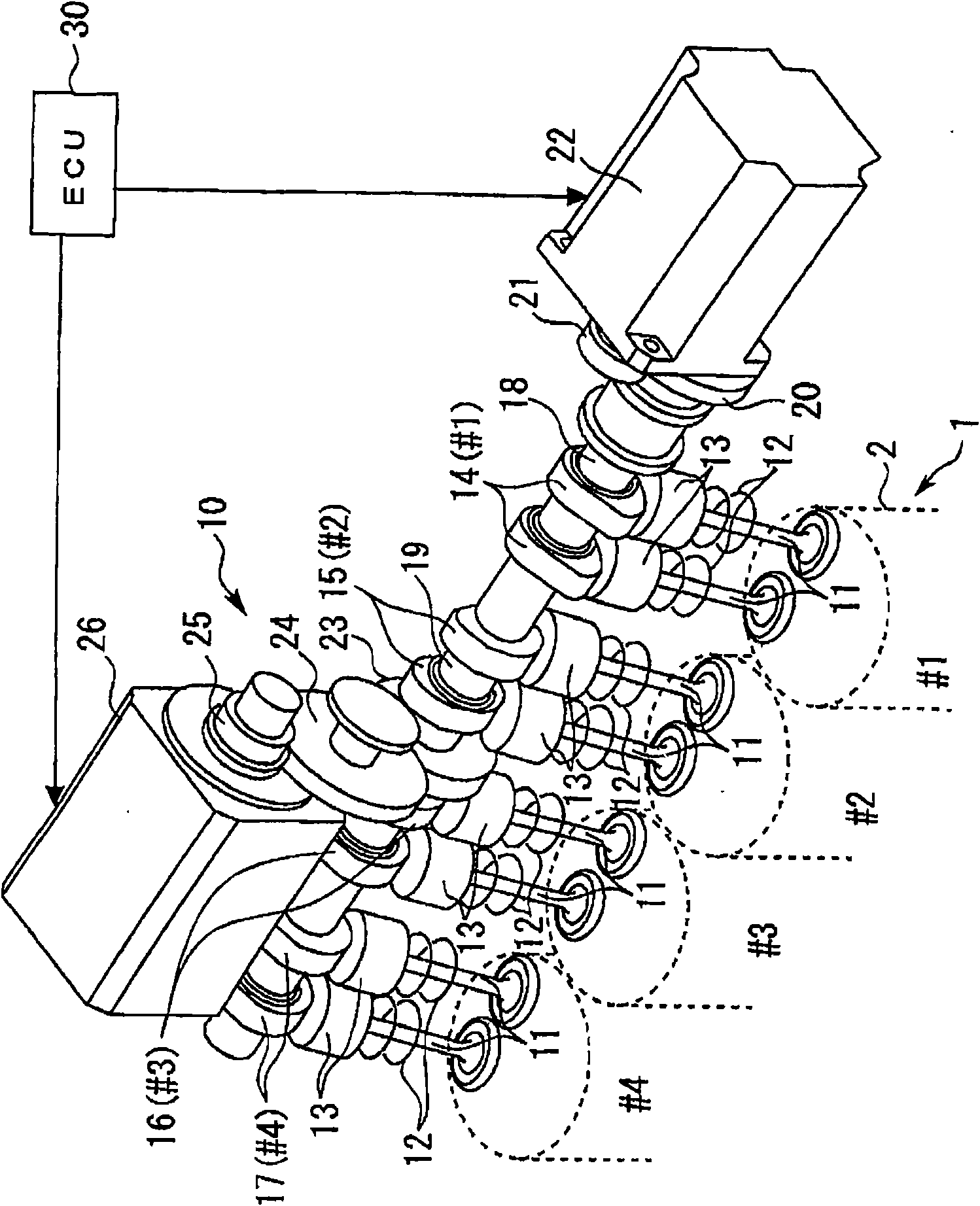
[0091] figure 1 It is a perspective view showing the configuration of the variable valve train 10 according to Embodiment 1 of the present invention. Such as figure 1 As shown, the variable valve mechanism 10 is provided on the intake valve 11 side of the engine 1 . The variable valve mechanism 10 can change the operating angle / lift amount of the intake valve 11 .
[0092] The engine 1 is, for example, an inline 4-cylinder gasoline engine. exist figure 1 Among them, #1 to #4 represent the first to fourth cylinders of the engine 1, respectively. The work order of the engine 1 is the same as that of a general engine, which is #1→#3→#4→#2.
[0093] The two intake valves 11 provided in each cylinder 2 are biased toward the valve lifter 13 by the spring reaction force of the valve spring 12 . On the top of each valve lifter 13, cams 14, 15, 16, 17 corresponding to each cylinder 2 are provided.
[0094] The cam 14 corresponding to t...
Embodiment approach 2
[0155] Next, refer to Figure 13 to Figure 16 Embodiment 2 of the present invention will be described.
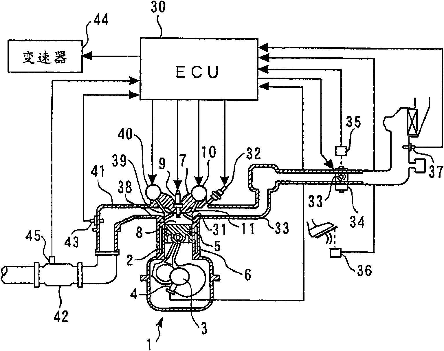
[0156] As the system of the second embodiment, it is possible to use Figure 1 to Figure 5 hardware shown.
[0157] Features of Embodiment 2
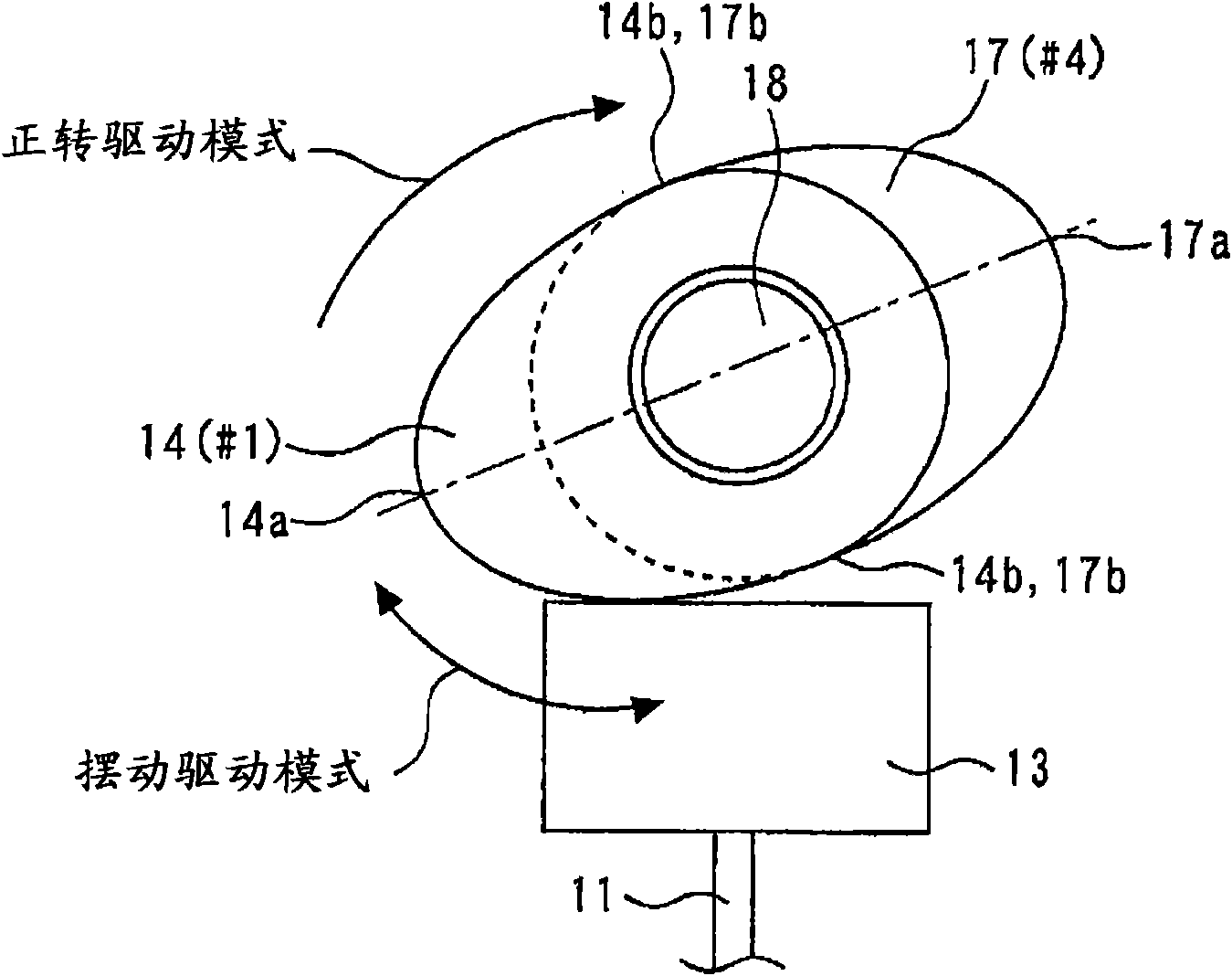
[0158] In the first embodiment described above, the case of the mode in which the cams 14 to 17 are driven in normal rotation has been described. On the other hand, in the second embodiment, the case of the mode in which the cams 14 to 17 are oscillatingly driven will be described. as reference figure 2 As illustrated, the system described above can be used and a swing drive mode implemented.
[0159] Figure 13 A to Figure 13 C is a graph showing the influence of the spring reaction force acting on the camshaft on the cam speed in the second embodiment. Figure 14 It is a figure which shows the graph which determines the target value of the cam rotation speed when the cam base circle slides. Figure 15 It is a figure which ...
Embodiment approach 3
[0166] Next, refer to Figure 17 and Figure 18 , Embodiment 3 of the present invention will be described.
[0167] As the system of the third embodiment, it is possible to use Figure 1 to Figure 5 hardware shown.
[0168] Features of Embodiment 3
[0169] For example, in the low rotation range where the engine speed NE is 2000 rpm or less, the camshaft rotational inertial force is smaller than in the high rotation range. Therefore, as in the present invention, when the spring reaction force is canceled out by the camshaft rotational inertial force, the amount of change in the camshaft rotational inertial force due to the spring reaction force becomes large. In this way, if Figures 10A to 10E as well as Figure 17 As shown, in the low rotation domain, the actual angle of action is enlarged compared with the high rotation domain. Figure 17 It is a graph showing the relationship between the engine speed NE and the actual operating angle in the third embodiment. exist ...
PUM
 Abstract
Description
Claims
Application Information
 - R&D
- Intellectual Property
- Life Sciences
- Materials
- Tech Scout
- Unparalleled Data Quality
- Higher Quality Content
- 60% Fewer Hallucinations
Browse by: Latest US Patents, China's latest patents, Technical Efficacy Thesaurus, Application Domain, Technology Topic, Popular Technical Reports.
© 2025 PatSnap. All rights reserved.Legal|Privacy policy|Modern Slavery Act Transparency Statement|Sitemap|About US| Contact US: help@patsnap.com


