Method for operating a reagent metering valve and apparatus for carrying out the method

A technology of metering valves and reagents, which is applied in the direction of noise reduction devices, exhaust devices, separation methods, etc., can solve the problems of incomplete reduction of nitrogen oxides, odor interference, high reagent consumption, etc., to avoid high temperature, low cost, and realize The effect of component protection

Active Publication Date: 2009-09-23
ROBERT BOSCH GMBH
View PDF4 Cites 5 Cited by
  • Summary
  • Abstract
  • Description
  • Claims
  • Application Information

AI Technical Summary

Problems solved by technology

Too little dosage for complete reduction of nitrogen oxides in the SCR catalyst
Dosing that is too high leads to reagent slippage, which on the one hand leads to an unnecessarily high reagent consumption and on the other hand to unpleasant odor disturbances depending on the properties of the reagents

Method used


Image

  • Method for operating a reagent metering valve and apparatus for carrying out the method

Examples


Embodiment Construction

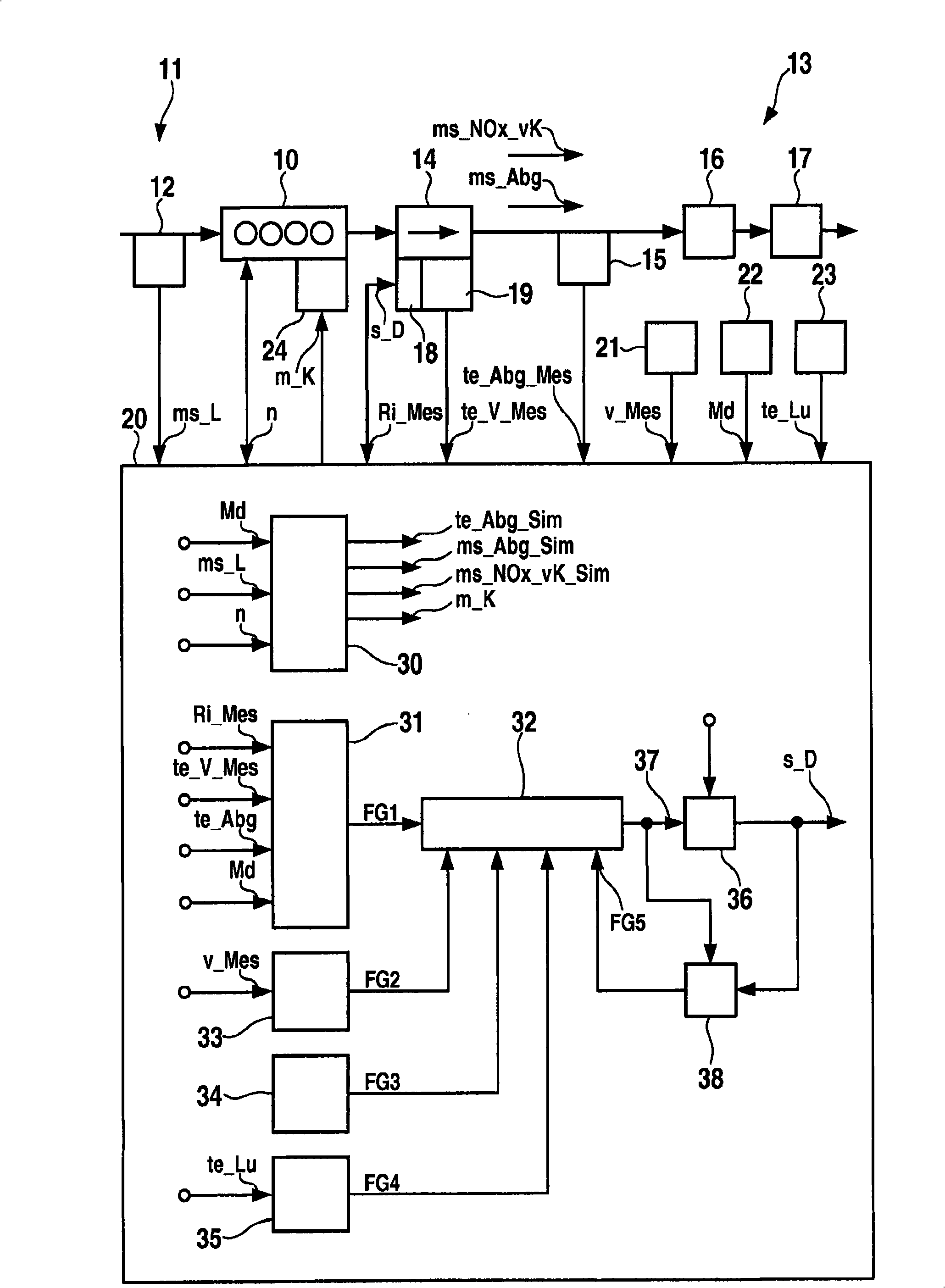
[0024] figure 1 An internal combustion engine 10 is shown, an air detector 12 is arranged in its intake region 11 and a metering device 14 , an exhaust gas temperature sensor 15 , a catalytic converter 16 and a particle filter 17 are arranged in its exhaust region 13 .

[0025] The exhaust gas mass flow ms_abg occurs in the exhaust region and the NOx mass flow ms_NOx_vK occurs upstream of the catalytic converter 16 .

[0026] The metering device 14 includes a solenoid valve 18 and a metering valve temperature sensor 19 .

[0027] Air detector 12 supplies air signal ms_L to control device 20 , internal combustion engine 10 supplies rotation signal n and exhaust gas temperature sensor 15 supplies measured exhaust gas temperature te_abg_Mes.

[0028] The solenoid valve 18 supplies the control unit 20 with a coil internal resistance Ri_Mes, and the metering valve temperature sensor 19 supplies the measured metering valve temperature te_V_Mes.

[0029] In addition, a speed sensor...


PUM


Abstract

The invention relates to a method for operating a metering valve (18) arranged in an exhaust gas region (13) of an internal combustion engine (10) for metering a reagent or a precursor of a reagent, comprising a cooling device to prevent excess temperatures. The invention further relates to a device for carrying out the method. During metering breaks of the regular metering process, a targeted predetermined minimum amount is metered for the cooling of the metering valve (18), if required.

Description

technical field [0001] The invention relates to a method for operating a reagent metering valve and a device for carrying out the method according to the preambles of the independent claims. [0002] A control unit program and a control unit program product are also the subject of the invention. Background technique [0003] In DE 199 03 439 A1 a method is described for operating an internal combustion engine, in the exhaust region of which an SCR catalytic converter (Selective-Catalytic-Reduction) is arranged, the SCR catalytic converter with a reagent Nitrogen oxides contained in the exhaust gas of the internal combustion engine are reduced to nitrogen. The metering of the reagents or precursors of the reagents preferably takes place as a function of operating characteristic variables of the internal combustion engine, such as the rotational speed and the injected fuel quantity. Furthermore, the dosing preferably takes place as a function of exhaust gas characteristic va...

Claims


Application Information

Patent Timeline
Patent Type & Authority Applications(China)
IPC IPC(8): F01N3/20F01N11/00B01D53/90
CPCF01N2610/03F01N3/0871F01N2550/05Y02T10/24F01N13/02F01N3/208Y02T10/47F01N9/002F01N2610/11F01N2610/02F01N13/009Y02T10/12Y02T10/40Y02A50/20
Inventor R·海伯勒M·霍恩
Owner ROBERT BOSCH GMBH
Why Eureka
Try Eureka