
Double-fold back projection imaging method for reflection tomography laser radar

A technology of lidar and reflection tomography, which is applied in the direction of using re-radiation, electromagnetic wave re-radiation, radio wave measurement system, etc., can solve the problems of long processing time and large calculation amount of spherical back projection filtering

Inactive Publication Date: 2009-09-30
SHANGHAI INST OF OPTICS & FINE MECHANICS CHINESE ACAD OF SCI
View PDF0 Cites 8 Cited by
  • Summary
  • Abstract
  • Description
  • Claims
  • Application Information

AI Technical Summary

Problems solved by technology

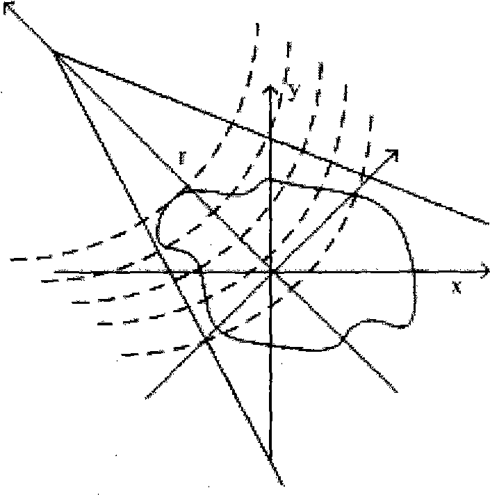
When the wavefront is bent, such as image 3 As shown in the reflection tomography lidar, the direct spherical back projection filtering method is computationally intensive and requires a long processing time

Method used

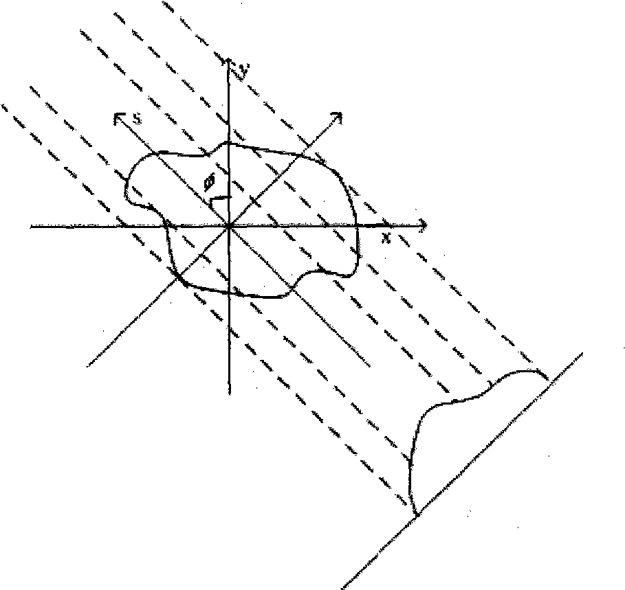
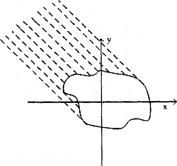

Image

  • Double-fold back projection imaging method for reflection tomography laser radar
  • Double-fold back projection imaging method for reflection tomography laser radar
  • Double-fold back projection imaging method for reflection tomography laser radar

Examples


Embodiment Construction

[0045] The present invention will be further described in detail below in conjunction with the accompanying drawings and examples, but the protection scope of the present invention should not be limited thereby.

[0046] A reflection tomography laser radar bifold back projection imaging method, comprising the following steps:

[0047] (1) From the three factors of the target size of the detected object, the distance resolution of the detector, and the laser pulse width τ, calculate the minimum projection angle sampling interval Δφ and the minimum sampling of a single projection required for complete reconstruction of the object according to the Nyquist sampling law Points N p ;

[0048] In actual selection, the distance resolution should be the lower resolution of the detector and the optical pulse as the system distance resolution, otherwise information will be lost. For example, for an oscilloscope with a detector bandwidth of 4GHz and a maximum sampling rate of 20GHz, the...


PUM


Abstract

The invention relates to a double-fold back projection imaging method for a reflection tomography laser radar, substantially to a method for approximating a back projection wave front as double fold lines, which comprises the following steps: back projecting spherical reflection projection signals received by a laser radar detector to the corresponding double fold lines, and reconstructing images through the double fold lines. Compared with direct spherical back projection, the method has the advantages that the calculation amount of back projection arithmetic of the double fold lines is small, and the operation is simple and easy to realize. The analog simulation shows that the method can replace the spherical back projection to finish image reconstruction of corresponding quality requirement.

Description

technical field [0001] The invention relates to reflection tomography lidar, in particular to a bifold line back-projection imaging method of reflection tomography lidar, which back-projects the measured spherical reflection projection signal to the corresponding bifold line by approximating the back-projected wave surface as a bifold line On the broken line, the double broken line back projection signal is used to complete the image reconstruction corresponding to the distance and quality requirements. Background technique [0002] In medical computer-aided tomography (abbreviated as CT), two-dimensional image reconstruction based on one-dimensional transmission projection information has been widely used and developed. The obtained one-dimensional transmission projection information reflects the difference in transmission coefficient of different parts inside the object under multiple different angles. The content of back-projection imaging is that the light intensity val...

Claims


Application Information

Patent Timeline
IPC IPC(8): G01S17/89
Inventor 金晓峰刘立人孙建锋周煜吴亚鹏严毅
Owner SHANGHAI INST OF OPTICS & FINE MECHANICS CHINESE ACAD OF SCI
Learn More