Solid-state structure comprising a battery and a variable capacitor having a capacitance which is controlled by the state-of charge of the battery

A technology of capacitors and capacitor plates, applied in the direction of variable capacitors, electrolytic capacitors, capacitors that change capacitance mechanically, etc.

Inactive Publication Date: 2009-09-30
KONINKLIJKE PHILIPS ELECTRONICS NV
View PDF1 Cites 4 Cited by
  • Summary
  • Abstract
  • Description
  • Claims
  • Application Information

AI Technical Summary

Problems solved by technology

This is significantly smaller than the aforementioned prior art MEMS structures

Method used


Image

  • Solid-state structure comprising a battery and a variable capacitor having a capacitance which is controlled by the state-of charge of the battery
  • Solid-state structure comprising a battery and a variable capacitor having a capacitance which is controlled by the state-of charge of the battery
  • Solid-state structure comprising a battery and a variable capacitor having a capacitance which is controlled by the state-of charge of the battery

Examples


Embodiment Construction

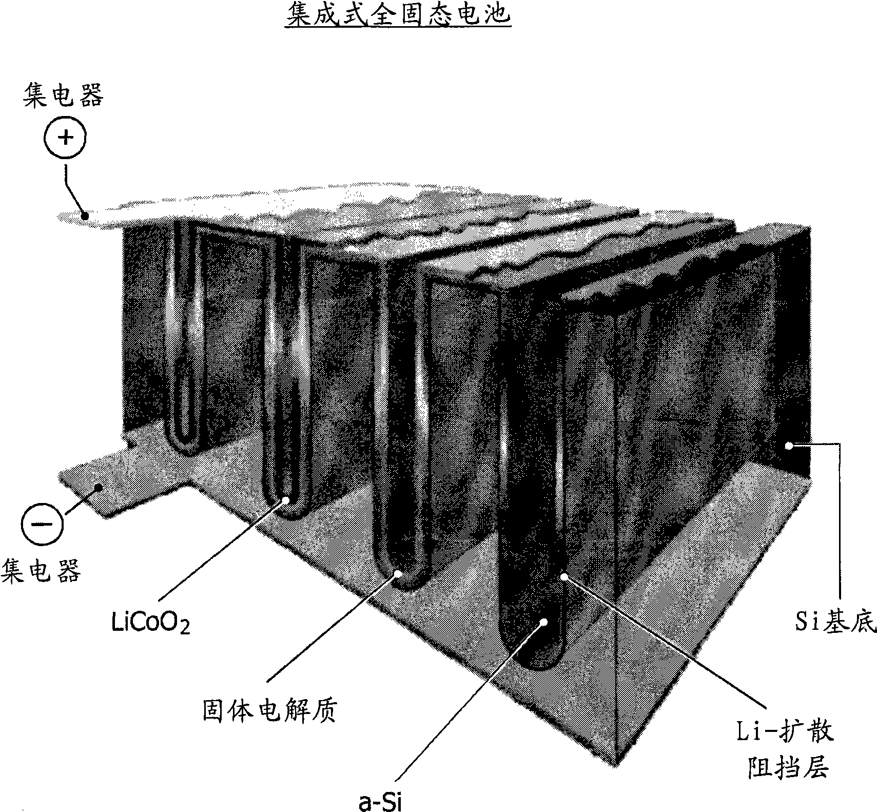
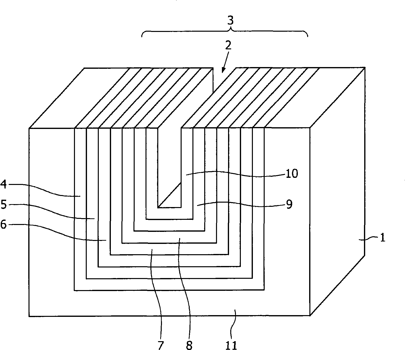
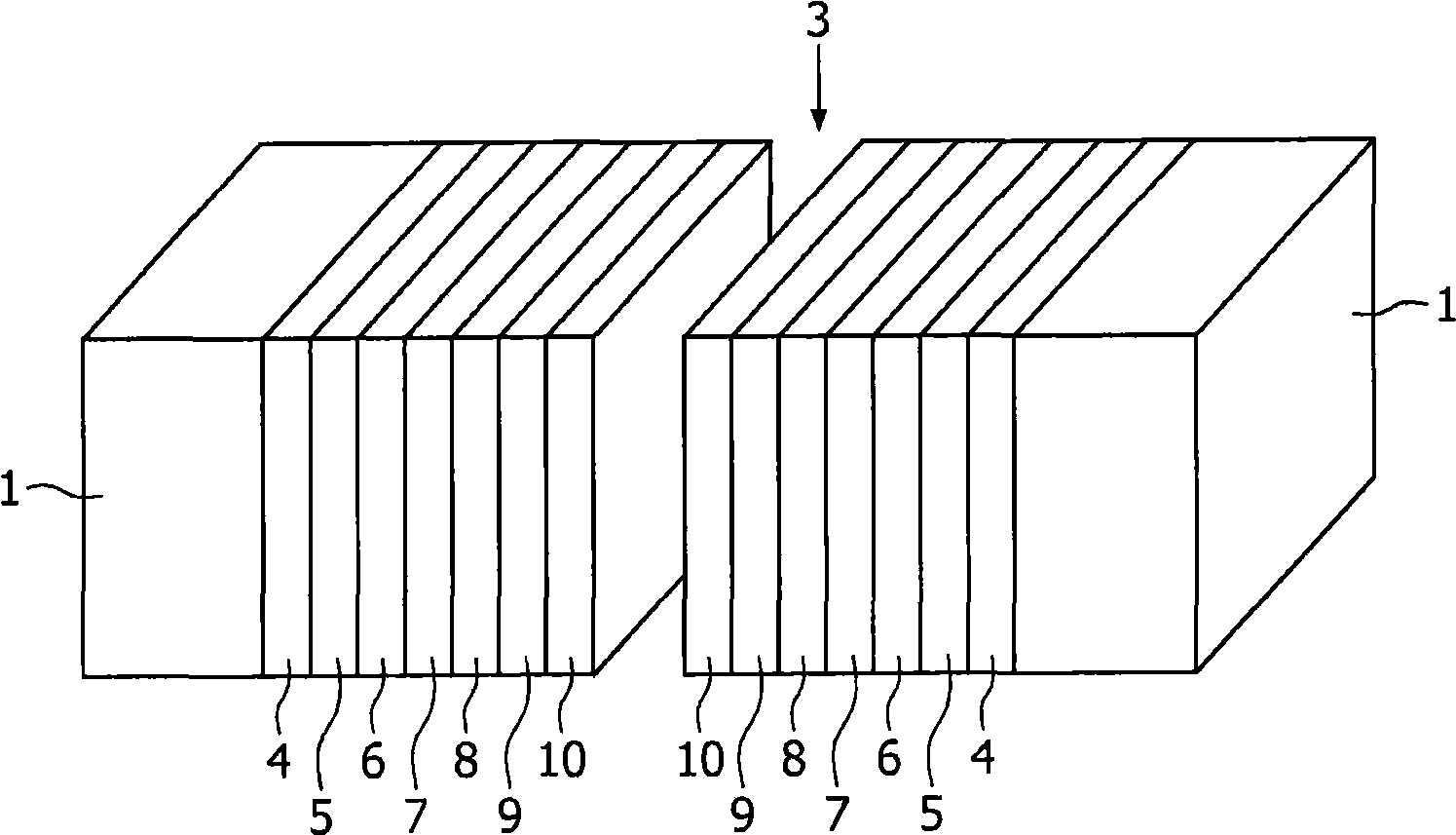
[0042] figure 1 An all-solid-state thin-film battery disclosed in document WO2005 / O27245A2 is shown. Using the deposition and integration techniques described in this prior art document, it is possible to make stacks that can be used to fabricate electrochemically tunable capacitors. The stack is in figure 2 shown in . In this figure there is shown a schematic view of a single trench in a substrate 1 in which a trench 2 is formed in which a cell stack, generally indicated at 3 , is deposited according to the prior art method described above.

[0043] This battery stack 3 applied to a substrate 1 comprises a current collector layer 4 , a cathode layer 5 , a solid electrolyte layer 6 and an anode layer 7 . On top of the anode layer 7 a current collector layer 8 is deposited. On the cell stack 3 thus formed is deposited a dielectric layer 9 on which is located a conductive layer 10 which will serve as a capacitor plate away from the current collector layer 8 . The dielectri...


PUM


Abstract

The present invention relates to a solid-state variable capacitor, comprising a first capacitor plate (10), a second capacitor plate (12), extending substantially parallel to the first capacitor plate (10) and on a distance from said first capacitor plate, wherein at least the first capacitor plate (10) is structurally coupled to one side of a first layered solid-state battery wherein the layers (4-8) of said first solid-state battery (3) extend substantially parallel to the first capacitor plate (10) and wherein the first solid-state battery is susceptible to variations in the size in the direction perpendicular to the plane of its layers (4-8). This invention is based on the realization that the thickness of a solid-state battery (3) varies with condit ions prevailing in the battery. The movable capacitor plate (10) causes a change of the capacitance value of the capacitor.

Description

technical field [0001] Currently, many variations of possible integrated capacitors are used in IC designs. However, depending on the circuit, it is generally desirable that at least some of these capacitors not have a constant value, but be variable or adjustable. Currently, there are controllable capacitors based on MEMS technology. These controllable capacitors are the microscopic equivalent of air-spaced variable capacitors and can be integrated into silicon using conventional wafer fabrication processes. In these devices, the capacitance value can be adjusted in a continuous manner by applying, for example, a DC voltage across the beam / membrane structure. Background technique [0002] While controllable or tunable MEMS capacitors have been extensively studied, these devices employ free-standing beams or membranes that tend to collapse or get stuck in a "closed" state. This may result from poor machining during undercutting of the beam or after application of too high...

Claims


Application Information

Patent Timeline
Patent Type & Authority Applications(China)
IPC IPC(8): H01G5/011H01G9/155H01M10/00
CPCH01G5/011H01M10/00H01M12/005H01M10/0436Y02E60/128Y02E60/10
Inventor R·A·H·尼森P·H·L·诺滕J·H·G·奥普赫特维尔德R·H·W·皮南伯格
Owner KONINKLIJKE PHILIPS ELECTRONICS NV
Why Eureka
Try Eureka