Inflatable punching method and punching equipment for micro-spraying belt

A technology of punching equipment and micro-spray belt, which is applied in metal processing and other directions, can solve the problems of cumbersome, inconvenient use, and inconvenient control, etc., and achieve the effects of ensuring pressure balance, fast and efficient drilling, and ensuring uniformity

Inactive Publication Date: 2014-07-16
刘士龙
View PDF9 Cites 0 Cited by
  • Summary
  • Abstract
  • Description
  • Claims
  • Application Information

AI Technical Summary

Problems solved by technology

Existing perforation technology on the micro-spray tape, instead of the situation of narrowed holes, closed holes and impermeable holes, the micro-spray tape will be pierced, so that two opposite surfaces of the micro-spray tape are sprayed with water. hole, so that it cannot be used normally
The fundamental reason is that the existing punching technology and punching equipment are not mature enough; for example, the patent No. CN200620116926.8 and the utility model patent named "Micro-spray belt punching machine" disclose a kind of continuous operation. Micro-spray belt punching machine, to overcome the existing pause punching technology, the punching principle is to place the synchronous shuttle in the micro-spray belt to achieve punching
During the use of this kind of equipment, the synchronous shuttle needs to be placed in the workpiece, which is not only cumbersome, but also not easy to control
It has the disadvantages of complex equipment, inconvenient use and low work efficiency

Method used


Image

  • Inflatable punching method and punching equipment for micro-spraying belt
  • Inflatable punching method and punching equipment for micro-spraying belt
  • Inflatable punching method and punching equipment for micro-spraying belt

Examples


Embodiment Construction

[0023] The present invention will be further described below in conjunction with the accompanying drawings and embodiments.

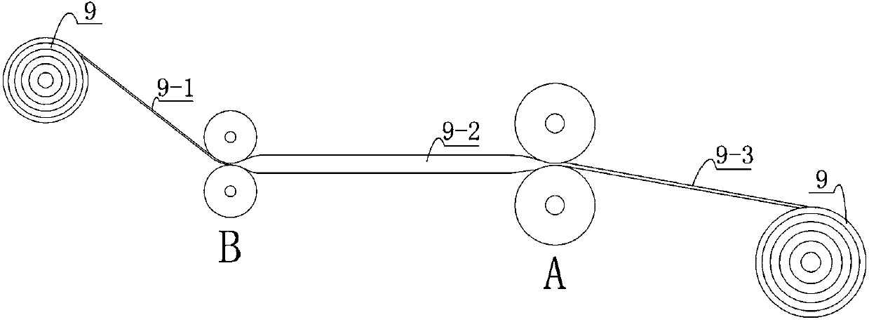
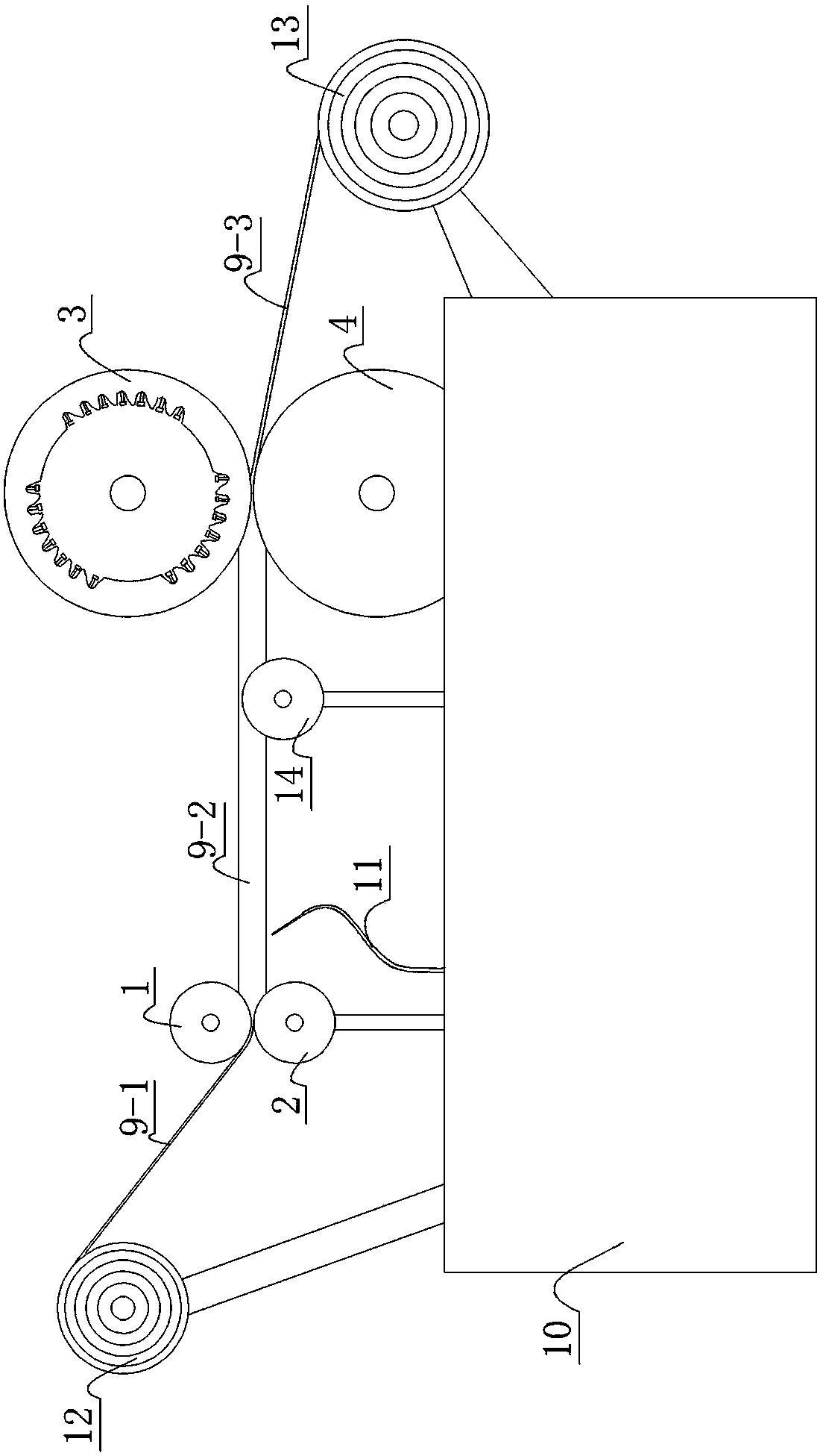
[0024] Combine below figure 1 The micro-spray belt inflatable punching method of the present invention is described, figure 1 Provided the principle diagram of the micro-spray belt inflatable punching method of the present invention, it comprises the following steps: a. extrude and seal, choose an end of the micro-spray belt to be perforated, adjacent to A and B at this end Carry out sealing with extruding device, so that the micro-spray belts on both sides of A place and B place both sides are not connected before perforating; And set A place at the front end of B place; Cooperating rolling wheels to squeeze and seal micro-spray strips. b. Inflate, fill gas into the micro-spray zone between A and B so that the upper wall and lower wall of the AB section of the micro-spray zone are not in contact; Spray belt (9-1), inflatable section micro spray belt...


PUM


Abstract

The invention discloses an inflatable punching method which comprises the following steps of: a, extrusion sealing: forming an AB segment in a sealed state; b, inflation: inflating into the AB segment of the micro-spraying belt; c, punching: punching on a single side in a state that the AB segment is airtight; d, traction: pulling out the punched micro-spraying belt; and e, finishing the punching of the whole micro-spraying belt. The punching equipment disclosed by the invention comprises two rear pressure rollers, a punching pressure roller and a front pressure roller; when in work, the micro-spraying belt between the rear pressure rollers and the front pressure roller is in an inflation state; and the punching pressure roller is provided with a punching device for punching on the wall of the micro-spraying belt attached to the punching pressure roller. Through the inflatable punching method and equipment disclosed by the invention, single-sided punching is realized, the situation of punching both sides of the micro-spraying belt is avoided, and the occurrence of narrow holes, closed holes and blind holes is avoided. By adopting the spraying irrigation of the micro-spraying belt, the beneficial effects of water conservation, energy conservation and uniform spraying irrigation can be realized; and the equipment has a reasonable structure and good beneficial effects and is convenient to popularize and use.

Description

technical field [0001] The invention relates to an inflatable punching method and punching equipment for a micro-spray belt, more specifically, to a punching method and punching equipment for single-side punching with a micro-spray belt in an inflated state. Background technique [0002] The pressure difference micro-water irrigation network is a systematic project integrating energy saving, water saving and micro-irrigation water delivery. In addition to requiring correct theory, reliable water delivery and stable water head, it must also ensure that the terminal emitters of the system ( That is, the water outlet holes on the micro-spray belt) are of the same size and cannot be blocked, so as to ensure uniform water outlet and stable and effective operation of the entire irrigation network. For example, the Chinese utility model patent with the patent number 200920089965.7 and the title of the invention "A Micro-irrigation Network Equipment for Pressure Difference Eliminati...

Claims


Application Information

Patent Timeline
Patent Type & Authority Patents(China)
IPC IPC(8): B26F1/24B26D7/08
Inventor 刘士龙李珂刘康
Owner 刘士龙
Why Eureka
Try Eureka