Three-stage dust chamber structure of spray-type dust collection tower

A technology for dust removal towers and dust removal chambers, which is applied in the separation of dispersed particles, chemical instruments and methods, and the use of liquid separation agents, can solve the problems of long dust removal pipes, easy blockage of dust removal devices, and high prices, and achieves good dust removal efficiency and dust removal. Efficiency No clogging, quick removal effect

Inactive Publication Date: 2009-10-07
WUXI XUEJIANG ENVIRONMENT ENG EQUIP
View PDF0 Cites 1 Cited by
  • Summary
  • Abstract
  • Description
  • Claims
  • Application Information

AI Technical Summary

Problems solved by technology

Among them, the bag filter is usually used for primary dust removal. Its dust removal ability is average, its energy consumption is extremely large, and its service life is very short. After 3 to 4 months of continuous dust removal, the dust removal bag will be blocked, and the tiny dust is not easy to remove; cyclone dust removal The dust removal pipeline of the electrostatic precipitator is long, and it is not easy to remove the tiny dust; although the dust removal effect of the electrostatic precipitator is good, it is expensive, and its dust removal device also has the problem of easy blockage

Method used


Image

  • Three-stage dust chamber structure of spray-type dust collection tower
  • Three-stage dust chamber structure of spray-type dust collection tower
  • Three-stage dust chamber structure of spray-type dust collection tower

Examples


Embodiment Construction

[0015] The present invention will be further described below in conjunction with specific drawings and embodiments.

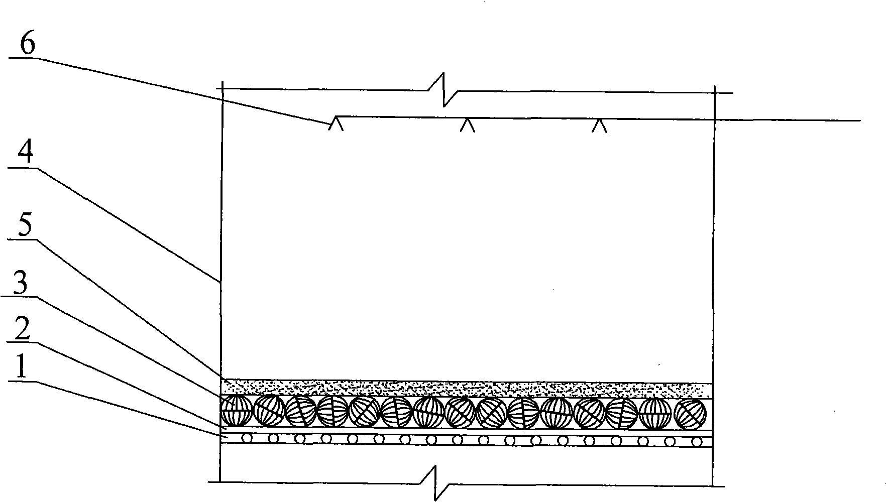
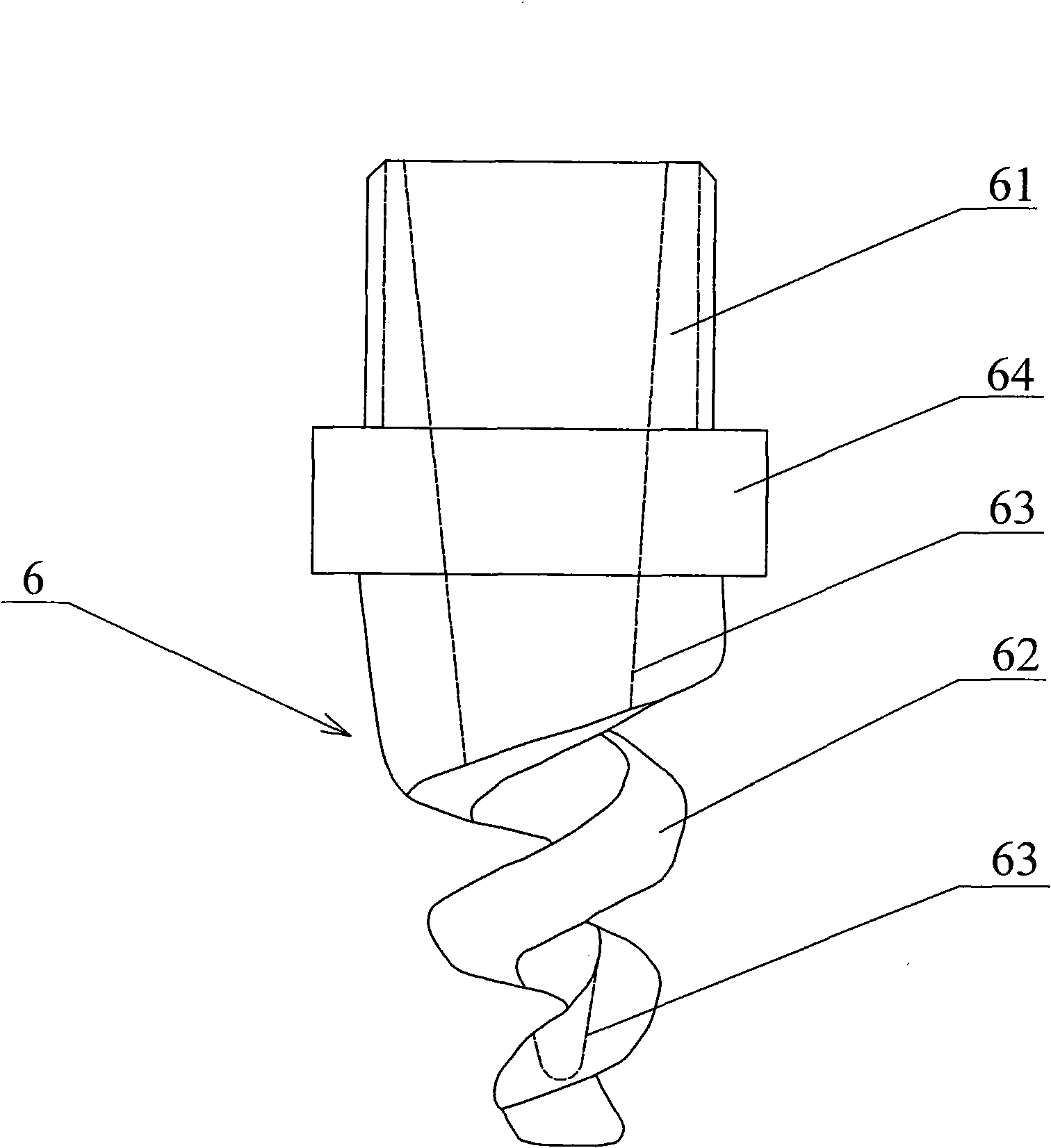
[0016] As shown in the figure: the structure of the three-stage dedusting room of the spray dedusting tower, which includes a support frame 1 fixed on the inner wall of the dedusting tower 4, the support frame 1 is covered with a corrosion-resistant net layer 2, and the corrosion-resistant net layer 2, the dust removal carrier ball 3 is laid, and the dust removal carrier ball 3 is covered with a spongy filter layer 5, and several spray heads 6 are erected in the dust removal tower 1 above the spongy filter layer 5.

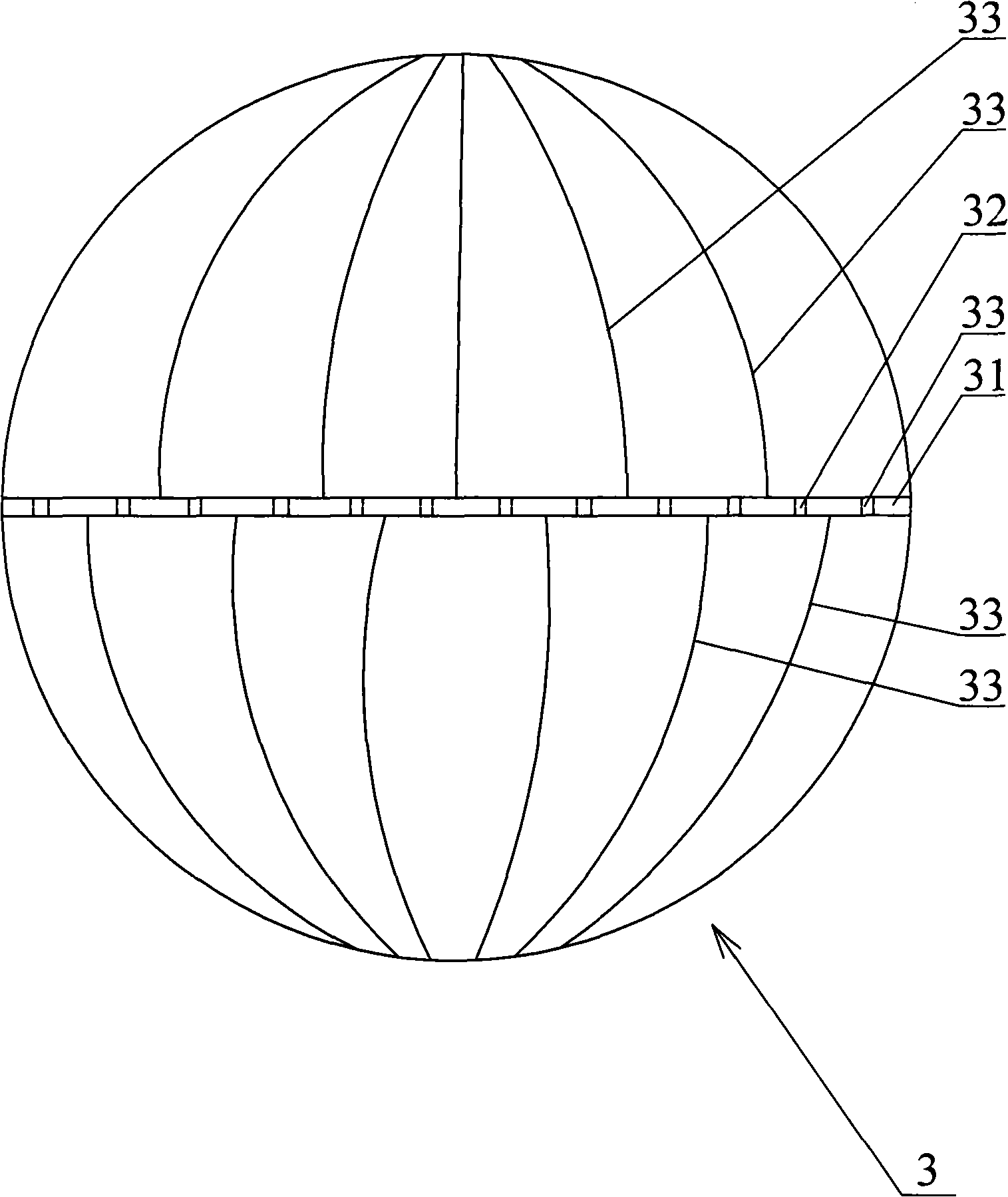
[0017] Described dedusting carrier ball 3 comprises the ventilation hole 32 that offers on the mounting plate 31, and several blades 33 are fixed on the upper and lower surfaces of the mounting plate 31, and the blades 33 roots on the upper and lower surfaces of the same mounting plate 31 are misplaced, and the air holes 32 The axis has a point of ...


PUM

PropertyMeasurementUnit
Taperaaaaaaaaaa

Abstract

The invention relates to a second-stage dust chamber structure of a wet dust collection tower. According to the technical proposal provided by the invention, a three-stage dust chamber structure of spray-type dust collection tower comprises a support foundation frame fixed on the inner wall of the dust collection tower, an corrosion resistant net-shaped layer covered on the support foundation frame, dust collection carrier balls paved on the corrosion resistant net-shaped layer, an spongy filtering layer covered on the dust collection carrier balls, and a plurality of spray heads arranged in an internal frame of the dust collection tower above the spongy filtering layer. After being installed and used, the dust chamber has the advantages of being capable of effectively and rapidly removing the dust from the smoke gas, high efficiency of dust removal, no blockage and the like.

Description

technical field [0001] The invention relates to a secondary dedusting chamber structure of a wet dedusting tower. Background technique [0002] At present, general enterprises mainly use dry dust removal equipment such as bag filter, cyclone dust collector and electrostatic precipitator for dust removal. Among them, the bag filter is usually used for primary dust removal. Its dust removal ability is average, its energy consumption is extremely large, and its service life is very short. After 3 to 4 months of continuous dust removal, the dust removal bag will be blocked, and the tiny dust is not easy to remove; cyclone dust removal The dust removal pipeline of the electrostatic precipitator is long, and it is not easy to remove the tiny dust; although the dust removal effect of the electrostatic precipitator is good, it is expensive, and its dust removal device also has the problem of easy blockage. Therefore, there is an urgent need for a wet dust removal device with better...

Claims


Application Information

Patent Timeline
IPC IPC(8): B01D47/06B01D47/14
Inventor 胡雪江
Owner WUXI XUEJIANG ENVIRONMENT ENG EQUIP
Why Eureka
Try Eureka