
Thermal connector for cooling electronics

Inactive Publication Date: 2005-04-19
HEWLETT PACKARD DEV CO LP
View PDF7 Cites 42 Cited by
  • Summary
  • Abstract
  • Description
  • Claims
  • Application Information

AI Technical Summary

Benefits of technology

[0003]The continued development of the microprocessor has led to significant increases in power dissipation requirements. System level performance requirements have resulted in computer systems that feature increasing numbers of microprocessors at very close proximity. The increase in system microprocessor count has reduced board to board spacing and, as a result, the available space available for thermal apparatus of computer systems.
[0008]In addition to serviceability, system reliability is of primary importance for business-critical, highly available, computer systems. System reliability is significantly increased by employing redundant components when necessary. The pump in a liquid loop is considered to be one of the least reliable components in a computer system and is therefore a prime candidate for redundancy. The addition of multiple redundant pumps to a liquid loop would further increase the weight of the assembly and hinder the serviceability requirement.
[0011]In various embodiments, the present invention solves some or all of the needs mentioned above by providing a cooling system that efficiently operates on one or possibly more high-dissipation devices with relatively simple maintenance. The combination of serviceability, reliability and redundancy make it highly desirable to de-couple a liquid loop assembly from electronics, thereby enabling easy removal of the processor board. This de-coupling can occur at the interface of the processor board and cold plates by means of a thermal connector. Such de-coupling would facilitate On-Line-Replacement of processor boards to further enhance system availability.
[0013]Advantageously, embodiments including this feature are preferably configured for rapid installation and / or removal of the circuit board without disassembling the cooling system. Instead, the actuator preferably can retract the cooling apparatus away from the heat sources so that the circuit board can be quickly removed and replaced. The actuator can then actuate the cooling apparatus toward the heat source to attain thermal contact. The system also provides for rapid and efficient initial installation of a circuit board.
[0014]In some embodiments the invention features first and second cooled bodies that are compliantly mounted to a first support. This allows the first support to be actuated toward the circuit board, while the first and second cooled bodies separately adapt to the height and / or position of the first and second heat sources, respectively. Advantageously, this provides for conforming thermal contact while allowing for height and / or tolerance differences.
[0016]The invention further features a second actuator configured to actuate a second cooling apparatus into conforming thermal contact with one or more heat sources on an opposing, second side of the circuit board with respect to the side having the first and second heat sources. Optionally, both the heat sources and the cooling system are symmetric across a plane defined by the circuit board, thereby balancing contact forces and potentially providing structural support while making thermal contact.

Problems solved by technology

The continued development of the microprocessor has led to significant increases in power dissipation requirements.
A disadvantage of employing a liquid loop to cool a computer system is the weight and bulk of the liquid loop assembly, which can exceed 30 lbs. per 600 W processor board.
The serviceability of a processor board that contained a liquid loop would be oppressive due to the excessive weight of the processor board, in combination with the liquid loop, and the inability of the processor to be quickly and easily detached from the cold plate.
The addition of multiple redundant pumps to a liquid loop would further increase the weight of the assembly and hinder the serviceability requirement.
Therefore, these solutions all require that the system be shut down prior to removal of the cooled component thus hindering serviceability and limiting system availability.

Method used


Image

  • Thermal connector for cooling electronics
  • Thermal connector for cooling electronics
  • Thermal connector for cooling electronics

Examples


first embodiment

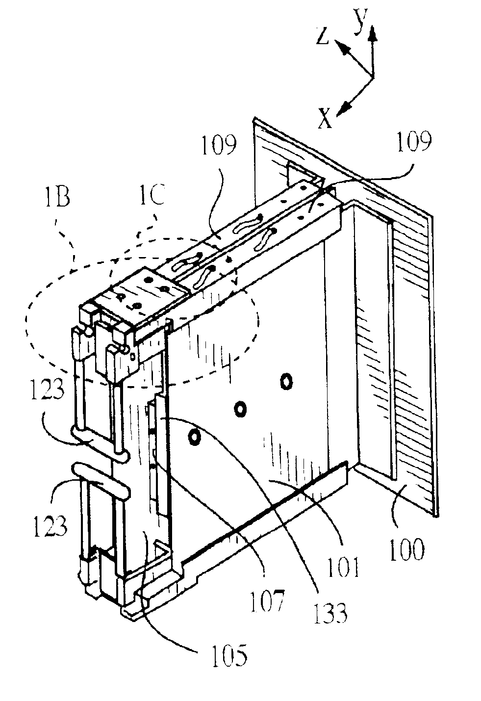
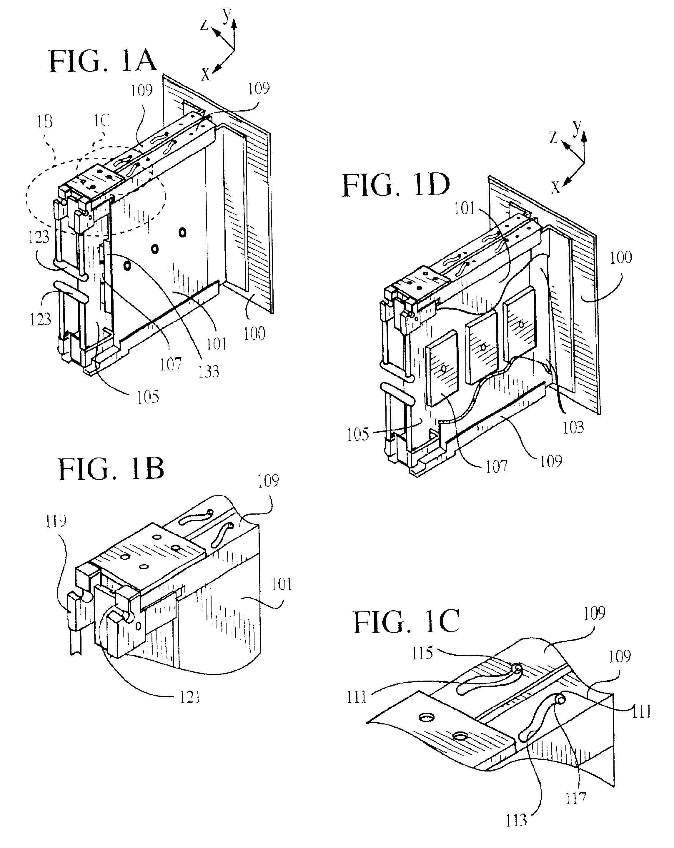
[0030]With reference to FIGS. 1A, 1B, 1C and 1D, attached to a substantially planar backplane 100, the invention comprises preferably two substantially planar actuation plates 101. The backplane includes a high-speed electrical connector 103 configured for connecting with a substantially planar processor board 105 having heat-producing components 107. The connector places the components in communication with a computer system. The actuation plates sandwich the processor board, and ride on rails 109 above and below the processor board. The rails are mounted to the backplane, and serve to attach the actuation plates to the backplane.

[0031]The actuation plates include guide pins 111 that slide in grooves 113 cut into the rails. Each groove forms a cam with each guide pin acting as cam followers in one groove. The combination of the cams and cam followers are designed to move the actuation plates in a lateral direction toward or away from the processor board (i.e., having a translationa...

second embodiment

[0050]With reference to FIG. 4, in the invention, a processor board 201 having heat-producing components 203 on one side can be cooled by a single cold plate 205. The cold plate can translate laterally along guides 207, and includes passages for working fluids, the passages being connected by tubes 209. The cold plate includes a thermally conductive body 211 composed of a compliant, gap-filling material, defining a contact surface 213 configured for thermally contacting the heat-producing components. This body 211 forms a compliant layer of thermally conductive material (i.e., a thermal interface) configured to adaptively place the cold plate in thermal communication with each heat-producing component, regardless of variations in its height off the processor board. The compliant layer of thermally conductive material is preferably a gap-filling thermal foam, which can adapt to surface and height variations. Preferably the compliant layer of thermally conductive material is adhesivel...

third embodiment

[0054]With reference to FIG. 6, in the invention, a processor board 301 carrying a plurality of heat-producing components 303 of different heights can include a layer of thermally conductive material 305 (i.e., a thermal interface) defining a single thermal-connection surface 307. The layer of thermally conductive material could be compliant or could be relatively rigid. Preferably the layer is formed by the process of spreading a liquid (i.e., not-yet solidified), gap-filling foam on the processor board, and letting it harden / solidify to partially encapsulate the heat-producing components. The thermal-connection surface is preferably a flat surface extending substantially parallel to the plane of the processor board. If the processor board includes heat-producing components on opposite sides of the board, as depicted, then a layer of thermally conductive material is preferably applied to each side of the processor board, effectively encapsulating a substantial portion of the proces...


PUM


Abstract

A modular semiconductor chip cooling system having a readily openable enclosure defining a chamber configured to hold a printed circuit board carrying components to be cooled. The enclosure can include a reservoir, a condenser and a pump. Sprayers within the chamber are adjustably mounted on one or more brackets to allow each sprayer to be set for the individual height of its respective component. The enclosure can be readily removed from a computer system through a quick release connection. The computer system can include a condenser and pump to operate all its modular cooling systems, removing the condensing function from the individual modules.

Description

[0001]The present application claims priority from U.S. provisional patent application, Ser. No. 60 / 271,273, filed Feb. 22, 2001, which is incorporated herein by reference for all purposes.[0002]This invention relates generally to cooling systems for heat-generating devices and, more particularly, to a thermal connector system for providing heat sink cooling to a heat-producing device.[0003]The continued development of the microprocessor has led to significant increases in power dissipation requirements. System level performance requirements have resulted in computer systems that feature increasing numbers of microprocessors at very close proximity. The increase in system microprocessor count has reduced board to board spacing and, as a result, the available space available for thermal apparatus of computer systems.[0004]A typical processor board can contain a multiplicity of CPU modules with associated cache memory, ASICs, and DC-DC converters. The total power dissipation from a si...

Claims


Application Information

Patent Timeline
IPC IPC(8): H05K7/20
CPCH05K7/20636
Inventor BASH, CULLEN E.PATEL, CHANDRAKANT D.SIMON, GLENN C.
Owner HEWLETT PACKARD DEV CO LP
Learn More