Electric welding machine

A welding machine and main circuit technology, applied in arc welding equipment, welding equipment, manufacturing tools, etc., can solve problems such as wasting power and affecting the life of electric welding machines

Inactive Publication Date: 2009-10-07
屈社文
View PDF0 Cites 0 Cited by
  • Summary
  • Abstract
  • Description
  • Claims
  • Application Information

AI Technical Summary

Problems solved by technology

[0002] When working with an electric welding machine, some auxiliary work is often done from one weld to the next. It wastes electricity and has an impact on the life of the welding machine

Method used


Image

  • Electric welding machine

Examples


Embodiment Construction

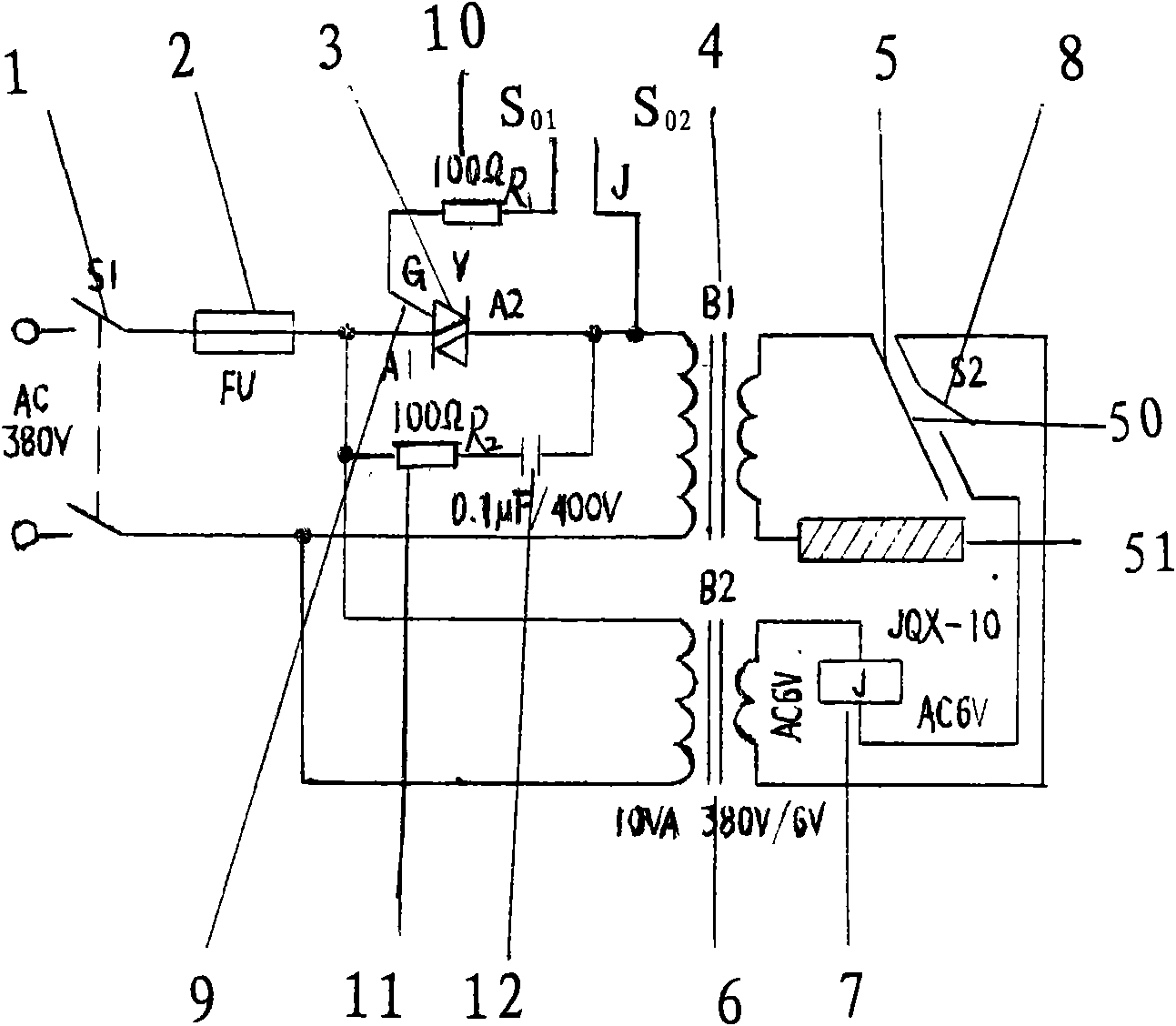
[0008] The present invention is described in detail below in conjunction with accompanying drawing: the circuit control of the present invention is mainly made up of main circuit and control circuit, and main circuit comprises power switch S 1 1. Fuse FU2, triac V3, small transformer B 1 4. Electric welding machine 5, etc.; the control circuit includes a small transformer B 2 6. Relay 7. Micro switch S 2 8. The trigger control pole G9 of the bidirectional thyristor and the current limiting resistor R 1 10 and contact S 01 , S 02 Bypass resistor R 2 11. Capacitor C12, etc.; power switch S 1 1. Connect to 380V AC power supply, fuse FU2 in the FireWire branch device, the outlet of fuse FU2 is connected to A of bidirectional thyristor V3 1 The terminals are connected, and the trigger control pole G9 of the bidirectional thyristor V3 is connected to a current-limiting resistor R 1 10, then connect its contact S 01 , while other contacts S 02 with the other end of the triac...


PUM

PropertyMeasurementUnit
electrical resistanceaaaaaaaaaa

Abstract

The invention provides an electric welding machine, comprising a main circuit and a control circuit; wherein the main circuit comprises a power switch S1, a fuse FU, a transformer B1 and the electric welding machine; the power switch S1 is connected with the fuse FU in series; the electric welding machine is connected on the auxiliary coil of the transformer B1; the main circuit also comprises a bidirectional triode thyristor V; the outlet end of the fuse is connected with the A1 end of the bidirectional triode thyristor V with a trigger control grade G; the other end of the bidirectional triode thyristor V is communicated with the primary coil of the transformer B1; simultaneously, the bidirectional triode thyristor V is connected in parallel to a bypass which is connected in series by a resistance R1 and a capacitor C; the control circuit comprises another transformer B2, a relay J1 and a micro-switch S2; the trigger control grade G of the bidirectional triode thyristor V and the micro-switch S2 is connected in series with the relay J and is communicated with the auxiliary coil of the transformer B2; the main coil of the transformer B2 is communicated with the fire wire of the outlet end of the fuse FU and the other end thereof is connected with a zero wire; the trigger control grade G is connected with a serially connected current-limited resistance R1; wherein the contact point is S01 and the other contact S02 is communicated with the other end A2 of the bidirectional triode thyristor V.

Description

Technical field: [0001] The invention relates to an electric welding tool, in particular to an electric welding machine. Background technique: [0002] When working with an electric welding machine, some auxiliary work is often done from one weld to the next. It wastes electricity and has an impact on the life of the welding machine. Invention content: [0003] The purpose of the present invention is to provide a new type of electric welding machine with simple circuit, economic benefits, convenient maintenance, reliable operation, and can have electricity when working, cut off the power supply when the welding work stops, and eliminate no-load loss. In order to achieve the above object, the present invention adopts the following technical scheme to realize, because the bidirectional thyristor can be turned on under the action of the positive and negative voltage of the power supply, and the control pole can be triggered under the action of positive and negative pulses, s...

Claims


Application Information

Patent Timeline
Patent Type & Authority Applications(China)
IPC IPC(8): B23K9/10
Inventor 屈社文
Owner 屈社文
Why Eureka
Try Eureka