Different-capacitance transformer paralleling alternate operation electricity-saving method and device

A technology of alternate operation and power-saving devices, applied in the direction of single-network parallel feeding arrangement, etc., can solve problems that affect power supply reliability, load loss cannot be saved, accidents are prone to occur, and achieve the reduction of complex and heavy switching operations, switching Rapid, timely and accurate, and the effect of improving the reliability of power supply

Active Publication Date: 2013-09-04
山东计保电气有限公司
View PDF4 Cites 1 Cited by
  • Summary
  • Abstract
  • Description
  • Claims
  • Application Information

AI Technical Summary

Problems solved by technology

In particular, the operation of changing the capacity of the capacity regulating transformer needs to be carried out in a power outage state. Every time the capacity of the capacity regulating transformer is changed, the user must be powered off. operational factors
[0005] The capacity of these original transformers does not conform to the actual situation, and the adjustment range is not enough. It can only save the no-load loss, and the load loss cannot be saved. The load loss is nearly ten times the no-load loss, and the energy consumption is even greater.
The failure of the transformer cannot be detected in time, and it can only be repaired by power outage, which affects the reliability of power supply and normal power consumption
The losses caused by planned power outages and unprepared sudden power outages are quite different
The load in different periods of the living quarters is very different, and the low load period is much larger than the high load period, which requires a change process for the transformer device, otherwise it is easy to cause huge losses or insufficient capacity, causing the transformer to burn out
In actual operation, the load of each phase of the three-phase power is different, and accidents are prone to occur
[0006] The existing constant-capacity transformer switching scheme needs to add too many transformers, and the investment cost is too high

Method used


Image

  • Different-capacitance transformer paralleling alternate operation electricity-saving method and device
  • Different-capacitance transformer paralleling alternate operation electricity-saving method and device
  • Different-capacitance transformer paralleling alternate operation electricity-saving method and device

Examples


Embodiment 1

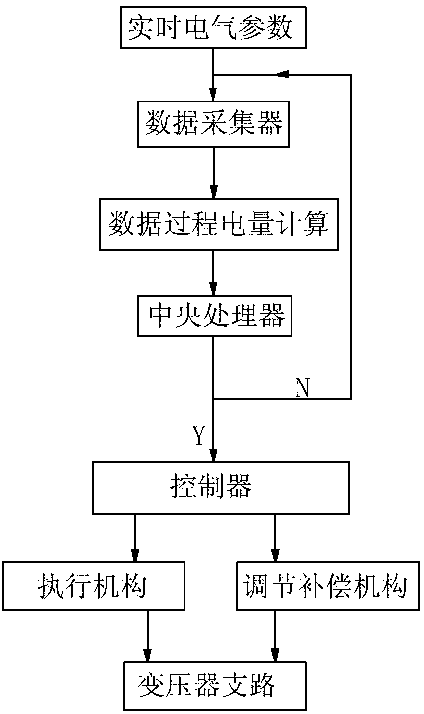
[0038] Such as figure 1 As shown, the method of parallel and alternate operation of different-capacity transformers includes the following steps:

[0039] (1) Collect the operating law of the load, and determine the maximum, minimum, and peak occurrence time periods during the load operation;

[0040](2) Set up two transformers with different capacities, switching controllers and adjustment compensation mechanisms according to the operating law of the load to form a large-capacity transformer branch and a small-capacity transformer branch. The capacity of the large-capacity transformer is greater than the maximum load, and the small-capacity The capacity of the transformer is greater than the minimum load;

[0041] (3) According to the operation law of the peak power load, the switching controller controls the adjustment and compensation mechanism, and adjusts and compensates the small-capacity transformer branch and the large-capacity transformer branch respectively until th...

Embodiment 2

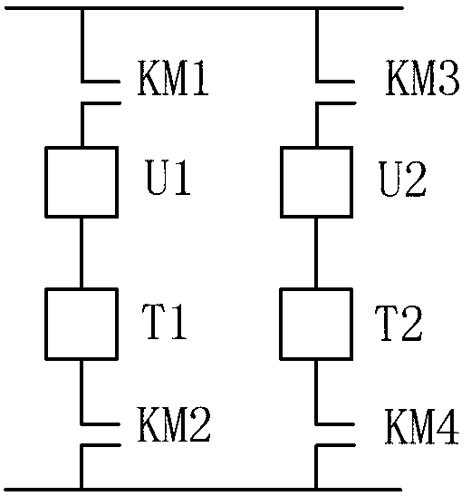
[0057] Such as Figure 4 As shown, on the large-capacity transformer branch, the controlled switch KM1, the transformer T1 and the controlled switch KM2 are connected in series in sequence. On the small-capacity transformer branch, the controlled switch KM3, the adjustment and compensation mechanism U1, the transformer T2 and the controlled switch KM4 are connected in series in sequence.

[0058] The contacts of the actuator (controlled switches KM1-KM4) are respectively connected to the primary side and secondary side of the large-capacity transformer and the small-capacity transformer, and the adjustment and compensation mechanism is only connected in series with the primary side of the small-capacity transformer.

[0059] When in use, the adjustment and compensation mechanism adjusts the branch circuit of the small-capacity transformer to switch.

Embodiment 3

[0061] In the above embodiments, the adjustment compensation mechanism includes a variable impedance element, the control end of the variable impedance element is connected to the data end of the central processing unit, and the output ends of the two groups of variable impedance elements are respectively connected to the primary side of the large-capacity transformer and the small-capacity transformer. .

[0062] Here is an example to illustrate how it works or how to use it:

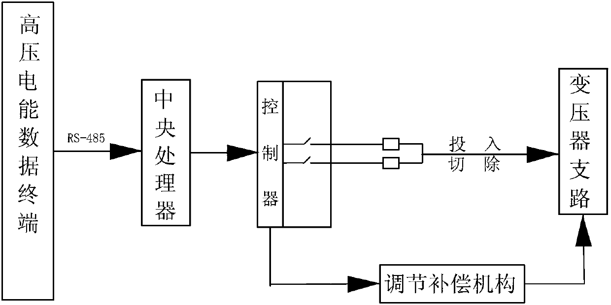
[0063] For example, by setting the high-voltage electric energy data terminal on the primary side of the transformer branch (its input terminal is set on the primary side of the transformer branch), the collected parameters are one or more of voltage, current, power, power factor and electric energy . Taking power as an example, the high-voltage electric energy data terminal collects the real-time power of the unit load. According to the maximum and minimum values, set up two high-capacity transforme...


PUM


Abstract

The invention discloses a different-capacitance transformer paralleling alternate operation electricity-saving method and device, and belongs to the field of intelligent electrical equipment. The different-capacitance transformer paralleling alternate operation electricity-saving method is characterized by comprising the following steps: gathering operation rules of loads, and confirming time periods when a maximum value, a minimum value and a peak value appear; arranging more than two transformers with different capacitances, a switching controller and an adjusting compensation mechanism, wherein the transformers with the different capacitances are switched in a flexible mode through the switching controller and the adjusting compensation mechanism; compensating and switching the transformers according to an electricity-consuming load peak operation rule, and enabling the capacitances of the transformers which are put in service to be slightly larger than electricity-consuming loads. The method and device has the advantages that the capacitances of the transformers are timely and precisely adjusted to achieve economical operation, operational loss of the transformers is effectively reduced, power supply is ensured due to the fact that the transformers are switched in the flexible mode, non-load loss can be effectively reduced, the device is applicable to places with largely-changed loads, and reliability of the power supply is increased.

Description

technical field [0001] The invention provides a power-saving method and device for parallel and alternate operation of different-capacity transformers according to load conditions, and belongs to the field of intelligent power equipment. Background technique [0002] Power system loads, especially living quarters, hospitals, schools, office buildings, and discontinuously operating factories and mines, undergo repeated peak-valley-peak changes every day, and a large amount of electricity is wasted during holidays. [0003] At present, the selection of transformer capacity is basically based on the method of referring to the peak capacity and the simultaneous rate. When the load is low, the operating capacity most of the time is only a dozen or even a few tenths of the high load. For transformers with large and small capacities, the no-load loss varies greatly, and the load loss is nearly ten times the no-load loss. For decades, in order to save the no-load loss, the transfor...

Claims


Application Information

Patent Timeline
Patent Type & Authority Applications(China)
IPC IPC(8): H02J3/38
Inventor 荣潇荣博
Owner 山东计保电气有限公司
Why Eureka
Try Eureka