Temperature-controlled resistor housing of preheating welding wire

A technology of resistance and welding wire, applied in welding equipment, arc welding equipment, manufacturing tools, etc., can solve the problems of low resistivity, low efficiency of non-magnetic material welding wire preheating temperature measuring line, complicated preheating process, etc., and achieve welding efficiency High, good preheating effect, simple process effect

Inactive Publication Date: 2009-10-07
HARBIN INST OF TECH
View PDF1 Cites 8 Cited by
  • Summary
  • Abstract
  • Description
  • Claims
  • Application Information

AI Technical Summary

Problems solved by technology

[0004] The purpose of the present invention is to solve some problems such as the low efficiency of preheating the temperature measuring line for the welding wire of low resistivity and non-magnetic material by means of resistance heating and high frequency induction, and the complicated process of directly preheating the welding wire by using the auxiliary TIG arc. Provides a preheating welding wire temperature control resistance sleeve

Method used


Image

  • Temperature-controlled resistor housing of preheating welding wire
  • Temperature-controlled resistor housing of preheating welding wire
  • Temperature-controlled resistor housing of preheating welding wire

Examples


specific Embodiment approach 1

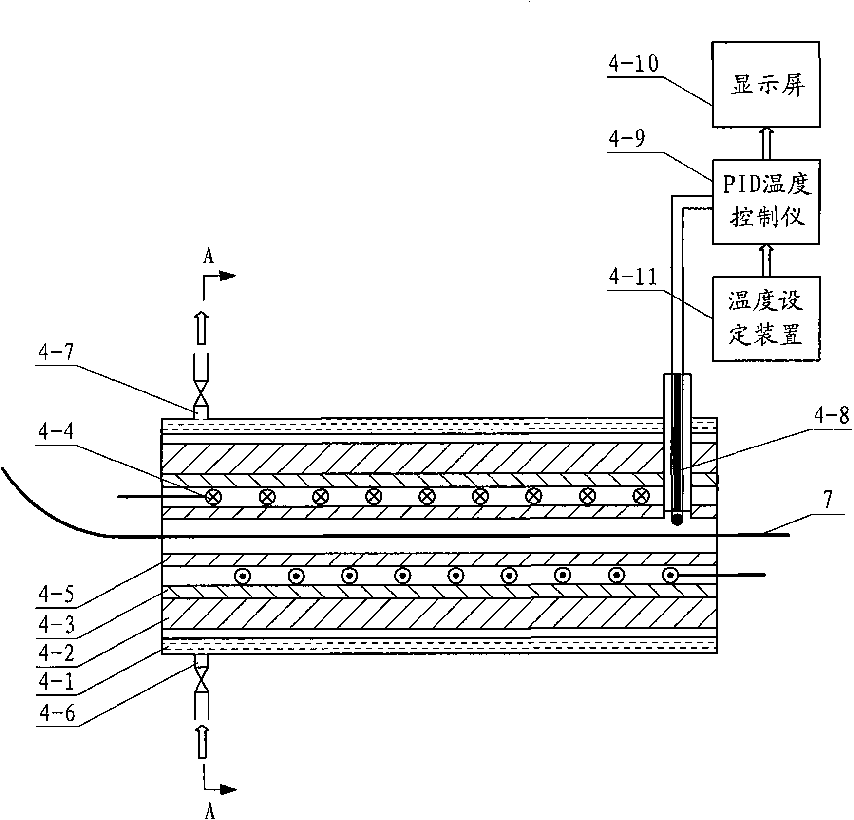
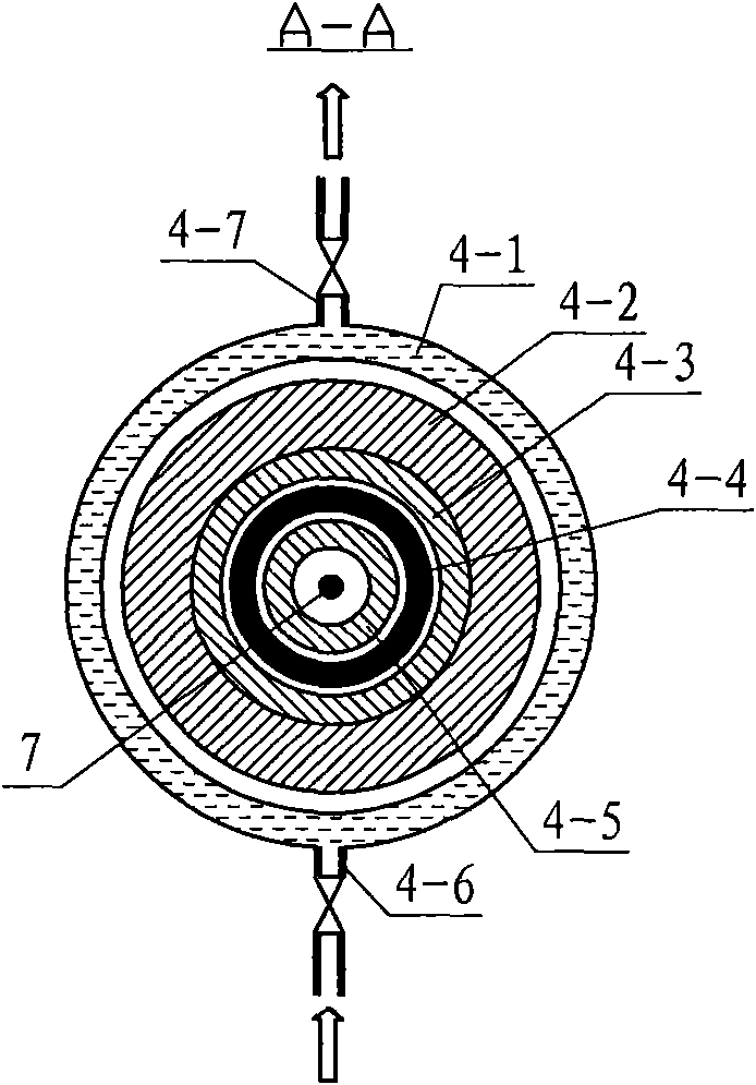
[0009] Specific implementation mode one: the following combination Figure 1 to Figure 3 To illustrate this embodiment, the preheating welding wire temperature control resistance sleeve 4 in this embodiment includes a cooling water jacket 4-1, a mica layer 4-2, an outer ceramic tube 4-3, a heating wire 4-4, and an inner ceramic tube 4- 5. An electric heating wire 4-4 is arranged between the water inlet pipe 4-6 and the water outlet pipe 4-7, the inner ceramic pipe 4-5 and the outer ceramic pipe 4-3, and the electric heating wire 4-4 is wound on the inner ceramic pipe 4-5, the outer surface of the outer ceramic tube 4-3 is provided with a mica layer 4-2, and the outer surface of the mica layer 4-2 is provided with a cylindrical cooling water jacket 4-1, cooling water jacket 4 The outer wall of -1 is provided with a water inlet pipe 4-6 and an outlet pipe 4-7 communicating with the outside world, which are used to enter and exit circulating cooling water.

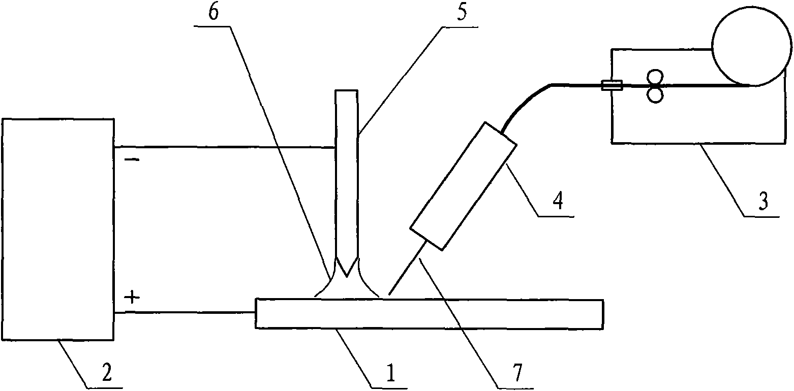
[0010] The TIG weldi...

specific Embodiment approach 2

[0014] Specific embodiment two: the difference between this embodiment and embodiment one is that it also includes a thermocouple 4-8 and a PID temperature controller 4-9, and the thermocouple 4-8 runs through the cooling water jacket 4-1 and the mica layer 4-2. The outer ceramic tube 4-3 and the inner ceramic tube 4-5, the temperature measuring end of the thermocouple 4-8 protrudes from the inner wall of the inner ceramic tube 4-5, and the cold end of the thermocouple 4-8 passes through the compensation The wires are connected to the PID temperature controller 4-9, and other components and connections are the same as those in Embodiment 1.

[0015] The thermocouple 4-8 monitors the temperature of the welding wire 7 passing through the cavity of the inner layer ceramic tube 4-5, and feeds back to the PID temperature controller 4-9.

[0016] The temperature control range of the PID temperature controller 4-9 is 50-400°C, and the control accuracy is ±5°C, that is, the temperatur...

specific Embodiment approach 3

[0017] Specific embodiment three: the difference between this embodiment and embodiment two is that it also includes a display screen 4-10 for displaying the temperature monitored by the thermocouple 4-8 and a temperature setting device for setting the temperature 4-11, the output end of the temperature setting device 4-11 is connected to the input end of the PID temperature controller 4-9, the output end of the PID temperature controller 4-9 is connected to the display screen 4-10, other components and connection relations It is the same as Embodiment 2.

[0018] The present invention controls the preheating temperature of the welding wire 7 through the PID temperature controller 4-9, and sets the preheating temperature of the welding wire 7 through the temperature setting device 4-11; the temperature of the welding wire 7 is controlled by the thermocouple 4-8 The temperature measuring terminal monitors it and feeds it back to the PID temperature controller 4-9, which is disp...


PUM


Abstract

A temperature-controlled resistor housing of preheating welding wire belongs to welding field. The aim of the invention is to settle the problems of low efficiency when the resistor heating and high-frequency induction method is adopted for preheating the low-resistivity and non-magnetic material welding stick and complicated technique for directly preheating the welding wire with an auxiliary TIG electrical arc. The temperature-controlled resistor housing of preheating welding wire according to the invention comprises a cooling water jacket, a specular stone layer, an outer ceramic pipe, an electric heating wire, an inner ceramic pipe, a water inlet pipe and a water outlet pipe. The welding wire is positioned in the inner ceramic pipe. The electric heating wire is positioned between the inner ceramic pipe and the outer ceramic pipe. The electric heating wire is winded at the outer surface of inner ceramic pipe. The outer surface of outer ceramic pipe is installed with the specular stone layer. The outer surface of specular stone layer is installed with a cylindrical cooling water jacket. The outer wall of cooling water jacket is installed with a water inlet pipe and a water outlet pipe for circulating the cooling water. The temperature-controlled resistor housing of preheating welding wire according to the invention is used for preheating the welding wire.

Description

technical field [0001] The invention relates to a temperature control resistance sleeve for preheating welding wire, which belongs to the field of welding. Background technique [0002] Ordinary tungsten argon arc welding (TIG) can no longer meet the welding efficiency and quality requirements of large-sized, thick-walled and special material welding components due to its weaknesses such as low deposition rate, slow welding speed, and large heat-affected zone. Hot wire TIG welding is an efficient TIG welding method. It preheats the welding wire on the basis of ordinary TIG welding, which speeds up the melting speed of welding wire and base metal, improves welding efficiency, and overcomes the common TIG welding. Defects such as porosity and lack of penetration. Moreover, the hot wire TIG welding speed is fast, which reduces the heat input and the superheat of the molten pool, reduces the range of the heat-affected zone, and is conducive to reducing welding deformation. [...

Claims


Application Information

Patent Timeline
Patent Type & Authority Applications(China)
IPC IPC(8): B23K9/235B23K9/16
Inventor 黄永宪吕世雄刘会杰冯吉才
Owner HARBIN INST OF TECH
Why Eureka
Try Eureka