Frame structure system
A frame structure and system technology, applied in the direction of building structure, construction, etc., can solve the problems of increasing the weight and stiffness of the structure, reducing the effective use area, increasing the cost of the building, etc., to improve the bearing capacity, protect the safety of people's lives and property, The effect of improving ductility
- Summary
- Abstract
- Description
- Claims
- Application Information
AI Technical Summary
Problems solved by technology
Method used
Image

Examples
Embodiment 1
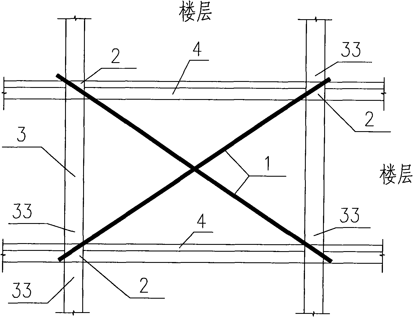
[0029] like figure 1 , figure 2 As shown, the present invention is applied to a reinforced concrete frame structure, and an oblique tie rod 1 is arranged between the upper and lower floors. to adjust the lateral stiffness of the floor. The connection between the column 3 and the floor 4 adopts a semi-rigid connection. The semi-rigid connection between the column end 33 and the floor 4 means that by reducing the number of column longitudinal reinforcements at the connection between the column 3 and the floor 4, the bending resistance of the connection is lower than that of the column 3, reduce the connection strength between column 3 and floor 4, but the joint can still bear a certain bending moment. Tie rod 1 can use high-strength steel strands or high-strength steel bars. Tie rod 1, column 3 and floor 4 form a truss type Anti-lateral force system, the tie rod 1 can be hidden in the partition wall.
Embodiment 2
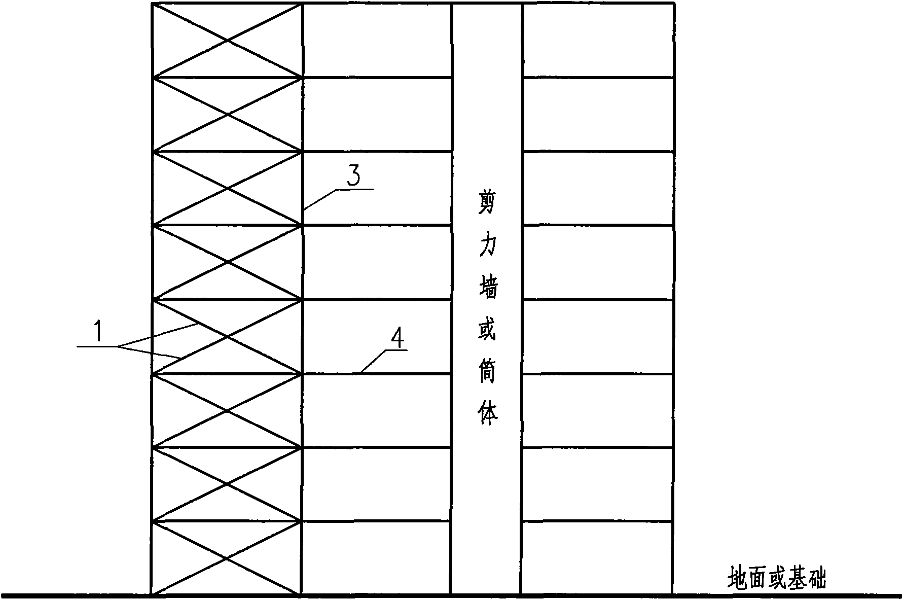
[0031] like image 3 As shown, the present invention is applied to a frame-shear wall structure or a frame-cylinder structure, and an oblique tie rod 1 is arranged between the upper and lower floors, and the two ends of the tie rod 1 are respectively fixed on the beam-column joints 2 of the upper and lower floors , adjust the lateral stiffness of the floor by applying prestress to tie rod 1. The connection between the column 3 and the floor 4 is hinged. The hinge connection between the column end 33 and the floor 4 means that the longitudinal reinforcement of the column is completely cut off at the connection between the column end 33 and the floor 4, and a steel bar or section steel is set at the center of the section of the column end 33 to connect with the floor. 4 are connected, and the column end 33 does not bear the bending moment. The tie rod 1 can be made of high-strength steel strand or high-strength steel bar. The tie rod 1, column 3 and floor 4 form a truss-type lat...
Embodiment 3
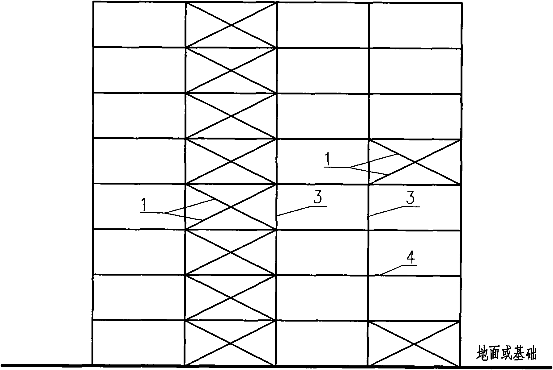
[0033] like Figure 4 As shown, the present invention is applied to the situation where the increase of the local story height of the building leads to the decrease of the lateral stiffness of the floor. Due to the needs of building use, the local floor height is relatively high, resulting in weak lateral stiffness of the floor. The tie rod 1 increases the stiffness of the floor. The two ends of the tie rod 1 are respectively anchored at the intersection of the floor 4 and the shear wall. The lateral stiffness of the floor can be adjusted by adjusting the prestress of the tie rod 1.
PUM
 Abstract
Description
Claims
Application Information
 - R&D
- Intellectual Property
- Life Sciences
- Materials
- Tech Scout
- Unparalleled Data Quality
- Higher Quality Content
- 60% Fewer Hallucinations
Browse by: Latest US Patents, China's latest patents, Technical Efficacy Thesaurus, Application Domain, Technology Topic, Popular Technical Reports.
© 2025 PatSnap. All rights reserved.Legal|Privacy policy|Modern Slavery Act Transparency Statement|Sitemap|About US| Contact US: help@patsnap.com