
Flow control system

A flow control, flow technology, applied in the direction of flow control, control/regulation systems, heating and ventilation control systems, etc., can solve problems such as energy waste, difficult to achieve, energy efficiency problems, etc.

Active Publication Date: 2009-10-07
YAMATAKE HONEYWELL CO LTD
View PDF2 Cites 5 Cited by
  • Summary
  • Abstract
  • Description
  • Claims
  • Application Information

AI Technical Summary

Problems solved by technology

[0006] However, in the conventional air-conditioning control system described above, there is a problem in terms of energy efficiency because the selected equipment has a maximum capacity that is somewhat more than the required design capacity.
For example, if the flow control valve has a surplus capacity, when it is intended to control the opening of the flow control valve, the maximum flow rate will flow more than the design flow rate when it is fully opened, and there will be a problem of energy waste.
In the past, there was no mechanism to quantitatively obtain this energy waste, and it was impossible to judge whether there was a problem in energy efficiency, and it was difficult to realize assembly for the purpose of energy saving

Method used


Image

  • Flow control system
  • Flow control system
  • Flow control system

Examples


Embodiment Construction

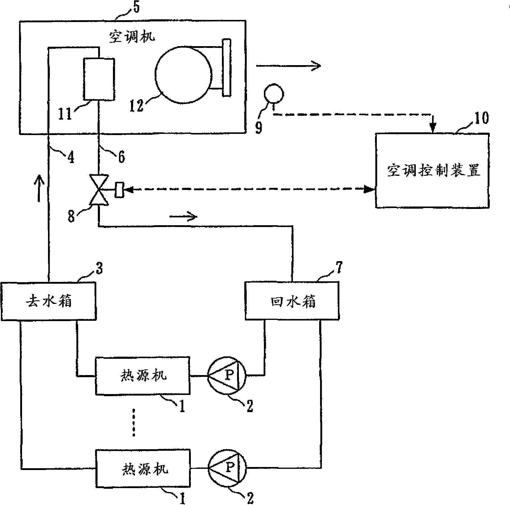
[0020] Hereinafter, the present invention will be described in detail with reference to the accompanying drawings. figure 1 It is an arrangement diagram of measuring instruments and control devices showing an example of an air-conditioning control system to which the flow rate control system of the present invention is applied.

[0021] figure 1 Among them, 1 is a heat source machine that generates cold and hot water, 2 is a pump that transports cold and hot water generated by heat source machine 1, 3 is a water removal tank that mixes cold and hot water from multiple heat source machines 1, and 4 is a water removal pipeline, 5 is the air conditioner that receives the supply of cold and hot water delivered from the water outlet tank 3 through the water outlet pipeline 4, 6 is the return water pipeline, and 7 is the heat exchanged in the air conditioner 5 and delivered through the return water pipeline 6. The return tank where cold and hot water returns, 8 is a flow control va...


PUM


Abstract

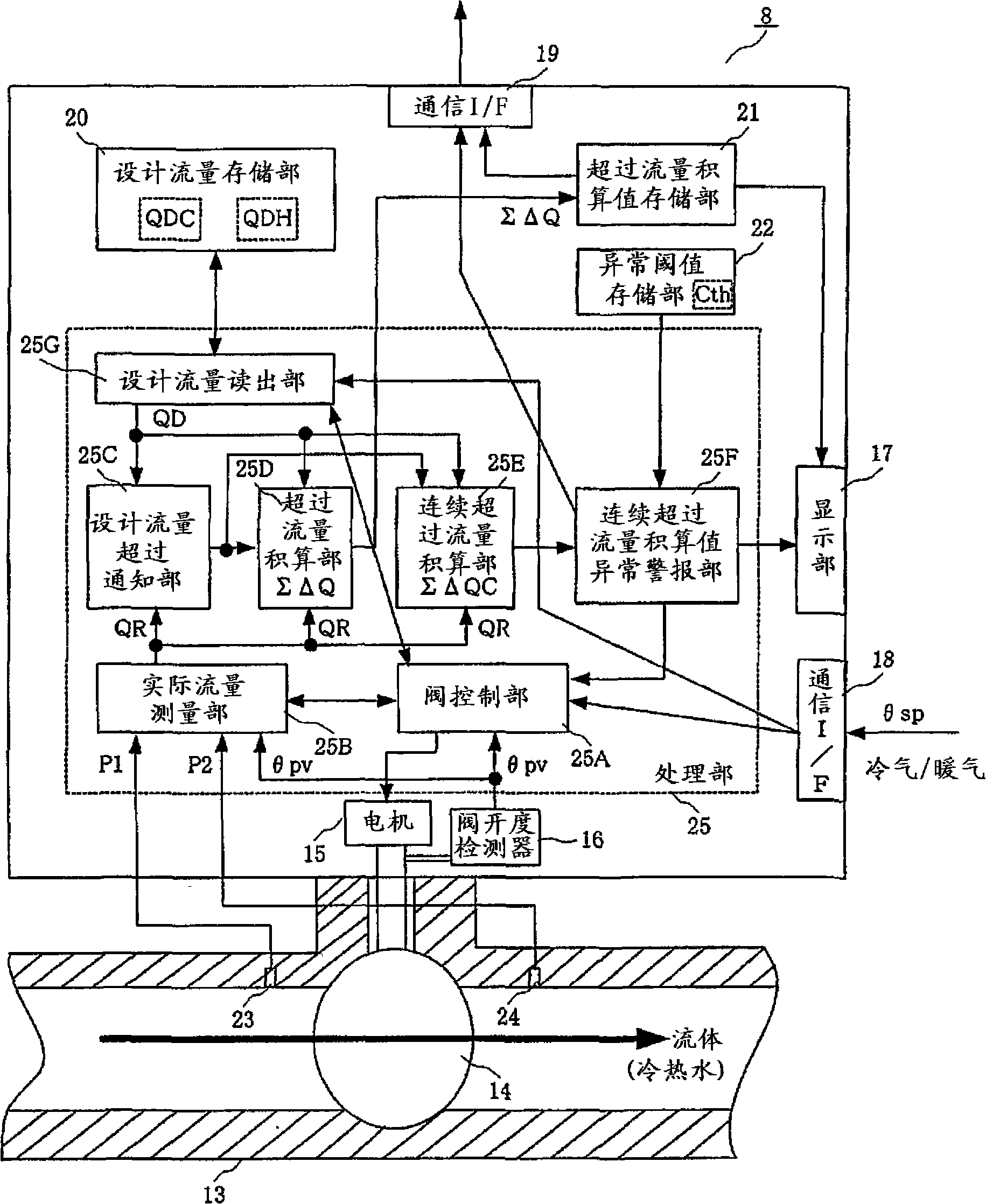
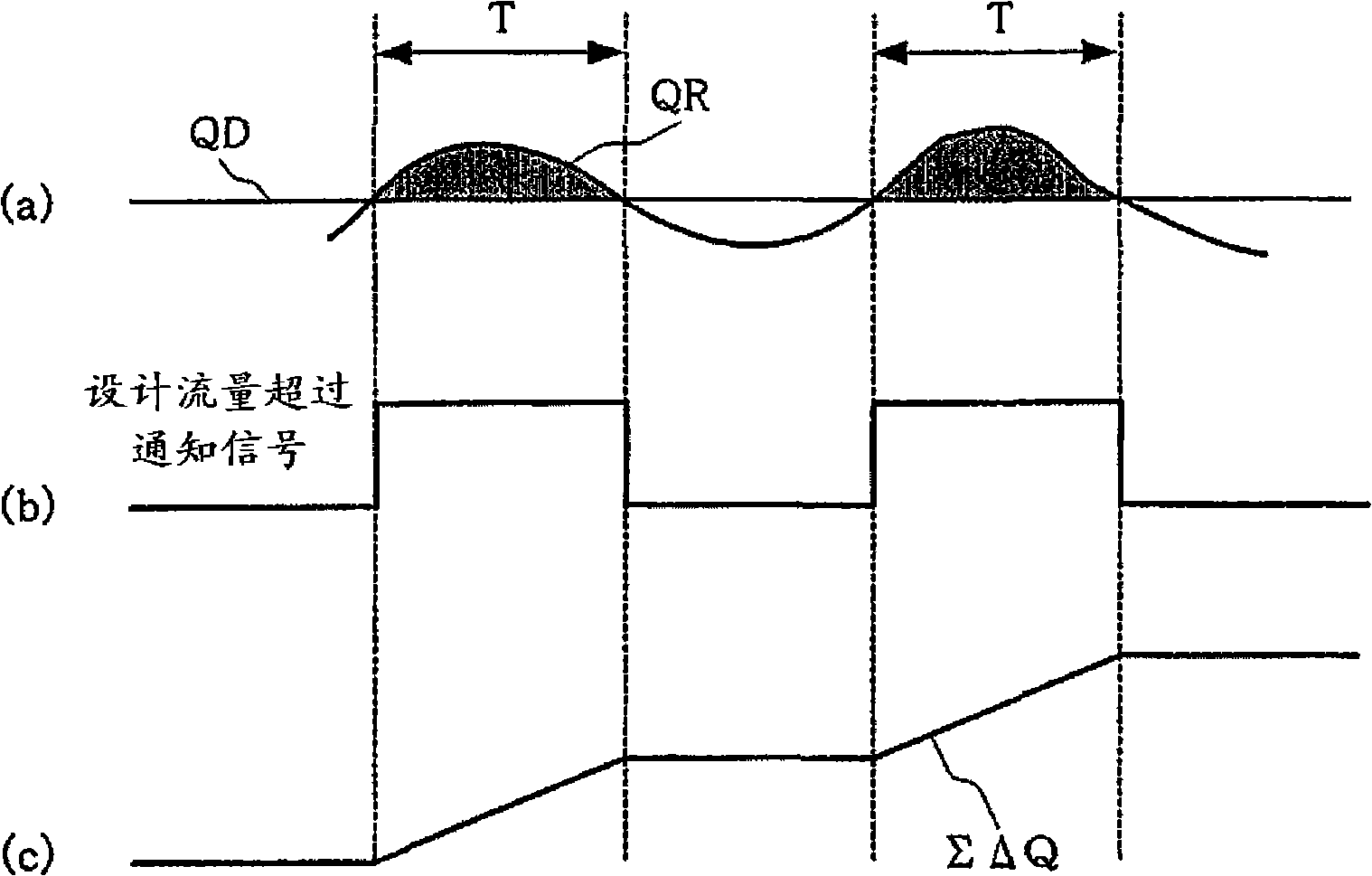
A flow control system is capable of quantificationally judging whether there is an energy efficiency problem or not and making an assembling for saving energy to being flexible. A actual flow (QR) of a fluid of a pipeline (13) is measured by an actual flow measurement part (25B). a exceed amount (Delta Q) of each exceed period that the fluid actual flow (QR) exceeds a design flow (QD) is reckonedby a exceed flow reckoning part (25D). A reckoning value (Sigma DeltaQ) of the exceed flow is stored in an exceed flow reckoning value storage part (21) and is displayed in a display part (17). Be means of referring to the reckoning value (Sigma DeltaQ) of the exceed flow, it is capable of knowing that the system is applied by a designed degree or by a degree that departures from a design. Moreover, by means of analyzing the reckoning value (Sigma DeltaQ) of the exceed flow, it is capable of detecting an energy extravagant degree of the system, or detecting whether there is an abnormity.

Description

technical field [0001] The present invention relates to a flow control system for controlling the flow of fluid flowing through a flow path. Background technique [0002] Conventionally, as such a flow control system, there is an air-conditioning control system that controls the flow rate of heat medium (cold and hot water) flowing into an air conditioner (for example, refer to Patent Documents 1 and 2). When constructing this air-conditioning control system, it is necessary to estimate the maximum amount of air-conditioning load (maximum air-conditioning load) in the area to be controlled to supply conditioned air from the air-conditioner, and to select, for example, a device that can eliminate the maximum air-conditioning load. Flow control valves that control the supply of heat source equipment, air conditioners, and cold and hot water from heat source equipment to air conditioners, etc. [0003] Here, if the capacity commensurate with the maximum air-conditioning load i...

Claims


Application Information

Patent Timeline
IPC IPC(8): F24F11/00G05D7/00G05B19/04
CPCF25B49/00F25B2600/2515F25B2341/06F25B41/30
Inventor 桂川智司
Owner YAMATAKE HONEYWELL CO LTD
Learn More