Method for measuring diameter of ring groove

A measurement method and detection method technology, applied in the direction of mechanical diameter measurement, etc., can solve the problems of inaccurate size measurement, inaccurate measurement, tilt measurement, etc., and achieve the effect of meeting the detection needs

Inactive Publication Date: 2009-10-07
力帆科技(集团)股份有限公司
View PDF0 Cites 10 Cited by
  • Summary
  • Abstract
  • Description
  • Claims
  • Application Information

AI Technical Summary

Problems solved by technology

However, the thickness of the block gauge generally does not match the width of the ring groove to be tested. There is a large gap between the upper and lower surfaces of the block gauge and the side wall of the ring groove, so the upper and lower surfaces of the block gauge are not easy to be parallel to the upper and lower side walls of the ring groove. It is easy to tilt in the groove to cause inaccurate measurement; and the two gauges must be parallel to each other in the length direction and tangent to the cylindrical surface of the bottom of the rin

Method used


Image

  • Method for measuring diameter of ring groove
  • Method for measuring diameter of ring groove
  • Method for measuring diameter of ring groove

Examples


Embodiment 1

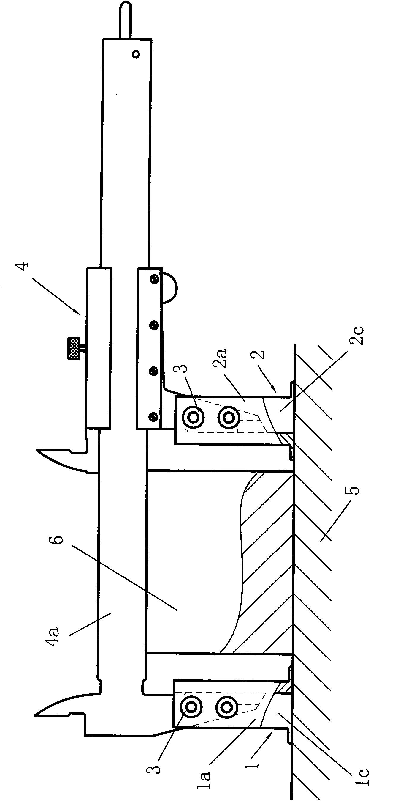
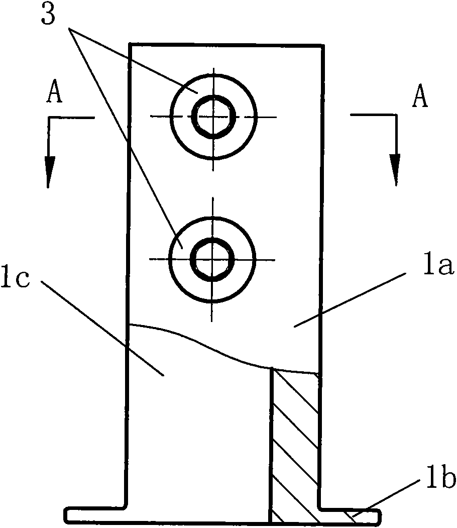
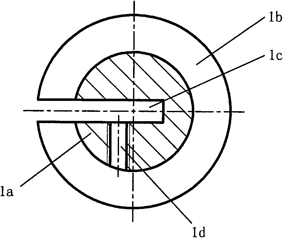
[0016] Embodiment 1: as figure 1 Shown, a kind of measuring method of ring groove diameter comprises installation method and detection method, carries out according to the following steps: (1) installation method, A, place a piece of contour pad iron 6 on flat plate 5, the external measurement of vernier caliper 4 The clips are respectively inserted into the through grooves of the left measuring pin 1 and the right measuring pin 2 with the same structure, so that the two measuring pins are set on the external measuring pins of the vernier caliper 4, and the height of the contour pad 6 is the length of the external measuring pins 1.4 times; B, place the lower surface of the ruler body 4a of the vernier caliper 4 on the top surface of the contour pad iron 6, and make the two external measuring pins vertically suspended on both sides of the contour pad iron 6, adjust The two measuring feet make the bottom surface of the flange at the lower end of the measuring feet stick to the f...

Embodiment 2

[0021] Embodiment 2: In the method for measuring the ring groove diameter described in this embodiment, the measuring foot used has the same structure as the measuring foot in Embodiment 1, and the measuring method is basically the same as that of Embodiment 1. The difference is that in During detection, the block gauge group formed by the combination of multiple block gauges is replaced by a block gauge close to the nominal size of the bottom diameter of the measured ring groove, and the length of the block gauge is first measured with the vernier caliper 4 equipped with the measuring feet, Note down the reading D 0 , and then use the method to measure the bottom diameter D of the tested ring groove 2 , the difference Δ obtained by subtracting the nominal size of the block gauge from the nominal size of the measured ring groove bottom diameter D Compensated to reading D 2 , get the value D 3 , ie Δ D +D 2 =D 3 , and finally the value D 3 with reading D0 Compare to dete...


PUM


Abstract

The invention relates to a method for measuring the diameter of a ring groove, which comprises an installing method and a detecting method. The measuring method comprises the following steps: placing the lower surface of the body of a vernier caliper on the top surface of a sizing block positioned on a flat plate, and making two outside tips vertically hang at two sides of the sizing block; fitting the bottom surface of the lower flanges of the measuring tips sleeved on the tips with the flat plate, and tightly screwing fastening bolts; when detecting, inserting the flanges of the two measuring tips from two sides of a measured ring groove until the flanges touch the bottom of the groove; finding the maximum value D2 generated when the shaft axis of the two measuring tips and the shaft axis of the measured ring groove are in the same plane; comparing the reading D2 with the standard value D1 of a block gage which is previously measured; and then, judging whether the measured value is within the tolerance limit or not. Each measuring tip comprises a column shaft provided with an axial through groove, and a coaxial thin disc-shaped flange positioned at the bottom end of the column shaft. The invention can accurately and conveniently detect the diameters of inner ring grooves and outer ring grooves of different sizes to meet the detection requirements of various workpieces.

Description

technical field [0001] The invention relates to a measuring method, in particular to a measuring method for detecting the diameters of inner and outer ring grooves. Background technique [0002] At present, there is no convenient and accurate measurement method for the outer ring groove processed on the outer cylindrical surface and the inner ring groove in the inner hole. For example, the piston ring is one of the key parts of the internal combustion engine. There are oil ring grooves and gas ring grooves on its outer surface to install the oil ring and gas ring. The oil ring groove and gas ring groove are collectively called the piston ring groove. The piston ring groove needs To control and detect the depth of the ring groove, in order to facilitate measurement, in actual processing, it is to control and detect the cylindrical diameter of the bottom surface of the piston ring groove, that is, the bottom diameter of the ring groove. At present, in production and batch tes...

Claims


Application Information

Patent Timeline
IPC IPC(8): G01B5/08G01B5/12
Inventor 王安武
Owner 力帆科技(集团)股份有限公司
Why Eureka
Try Eureka