Supercharge Your Innovation With Domain-Expert AI Agents!

Electric component

An electrical component, current technology, applied in electrical components, transformer/inductor components, circuits, etc., can solve problems such as damage, degraded magnetic performance, overheating, etc.

Inactive Publication Date: 2012-08-29
MDEXX
View PDF4 Cites 0 Cited by
  • Summary
  • Abstract
  • Description
  • Claims
  • Application Information

AI Technical Summary

Problems solved by technology

Since both welds and rivets have significantly worse magnetic properties, most will greatly deteriorate electromagnetic properties
Especially due to the additional losses caused by the eddy currents formed
This can cause localized overheating at higher frequencies, which in the worst case can lead to destruction

Method used


Image

  • Electric component
  • Electric component
  • Electric component

Examples


Embodiment Construction

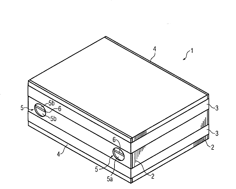
[0017] figure 1 A plate stack 1 of an electrical component is shown, which can be a transformer or an inductor. The electrical component includes a ferromagnetic core fitted with at least one coil such that a magnetic flux (not shown) is generated in the core when current flows through the coil.

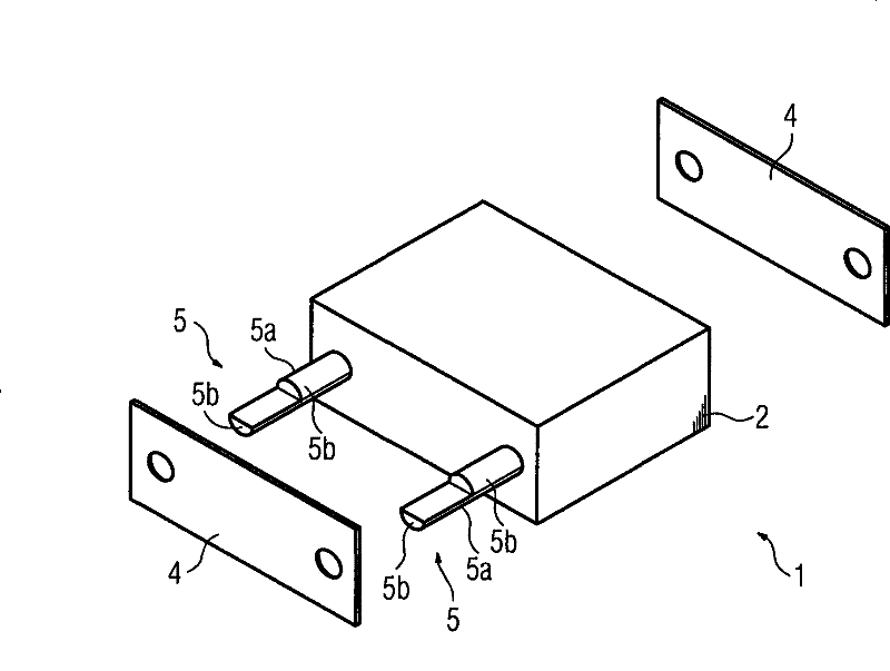
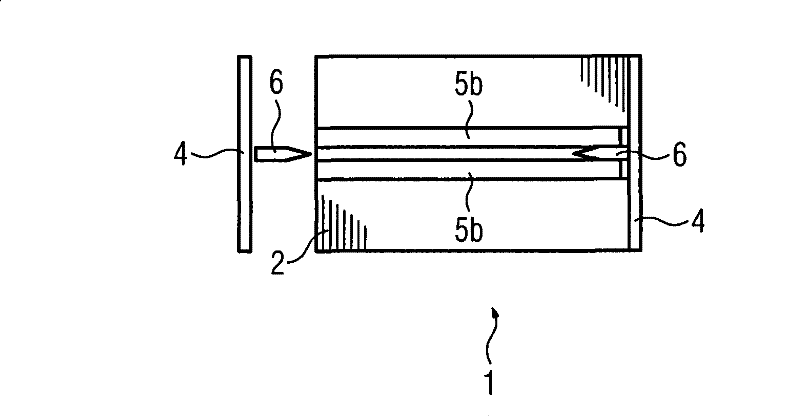
[0018] The core consists of at least one laminated core 1 which consists of ferromagnetic plates 2 which rest against each other with their planar sides. board 2 in figure 1 Indicated by thin dashes. as by figure 1 It can be seen that the relatively thin plate has a rectangular shape. The panels 2 are joined together by two straps 3 which rest on the outside and surround the stack 1 of panels. The tie hoop 3 can be an adhesive tape. A non-ferromagnetic plate 4 , such as an aluminum cover plate, is located on the two outer sides of the laminated core 1 . The plates 3 and 4 have two circular through-holes extending transversely through the plates, into which are inserted cylindr...


PUM


Abstract

The present invention relates to an electrical component, in particular, to a transformer or a choke, having a ferromagnetic core and at least one coil. A current flow through the coil generates a magnetic flow in the core. The core is composed of a number of ferromagnetic plates (2) against each other on plane sides forming at least one plate packet (1), held together by at least one bandage (3)against the outside. To implement the plate packet (1), single plate will not slide almost under any situation, that is, the magnetic characteristic of the core plate and the plate packet will not deteriorate. The plate packet (1) has at least two openings through the plates (2) transversely for non-magnetic units (5) in correspondence with the section of the opening respectively and connected with the plate packet (1) securely via separation of mutual pressure of at least one end thereof.

Description

technical field [0001] The invention relates to an electrical component, in particular a transformer or choke. Background technique [0002] Electrical transformers and chokes are well known and generally referred to as windings. They can have a ferromagnetic core with a plurality of legs, which are equipped with one or more coils or windings. The core often consists of parallel ferromagnetic core plates abutting against each other, which form a laminate stack. Slippage of individual core plates may occur in the core column during vibration and shock loading. This can happen when a core plate eliminates a stem air gap and can cause localized overheating due to magnetic flux based on large magnetic induction. A loose core may also be damaged due to the vibrations that occur. Problems can also arise when the core stack height is reduced due to air gap distribution and / or when high quality grain oriented boards are installed. [0003] For this reason, the plate pack is bou...

Claims


Application Information

Patent Timeline
Patent Type & Authority Patents(China)
IPC IPC(8): H01F27/26H01F27/245
CPCH01F41/0233H01F27/08H01F27/245
Inventor 马克·布勒斯克迪特尔·黑勒斯特凡·迈因克
Owner MDEXX
Features
  • R&D
  • Intellectual Property
  • Life Sciences
  • Materials
  • Tech Scout
  • Unparalleled Data Quality
  • Higher Quality Content
  • 60% Fewer Hallucinations
Learn More