Protective circuit of a control and protection switch

A protection switch, protection circuit technology, applied in emergency protection circuit devices, protection against overcurrent, computer control, etc., can solve the problems of difficult setting, low precision, poor reliability, etc. Simple circuit connection and high reliability

Inactive Publication Date: 2009-10-07
浙江中凯科技股份有限公司
View PDF5 Cites 18 Cited by
  • Summary
  • Abstract
  • Description
  • Claims
  • Application Information

AI Technical Summary

Problems solved by technology

[0003] Patent No. 01238478.X is a utility model patent "an integrated control and protection switching device". Its phase failure, overload, and overcurrent are realized by thermal magnetic modules, and thermal protection is realized by bimetallic strips. There is a precision Low, difficult to set, poor reliability, and difficult to carry heavy loads;
[0004] The invention patent with the publication number CN 1988098A "Control Device for Digital Control and Protection of Switching Appliances" discloses a CPS control device, the protection of which is realized by an embedded microprocessor, but the man-machine interface uses potentiometers and buttons, which is not very friendly , and no communication function
[0005] The patent for invention with the publication number CN 101047084A "

Method used


Image

  • Protective circuit of a control and protection switch
  • Protective circuit of a control and protection switch
  • Protective circuit of a control and protection switch

Examples


Embodiment Construction

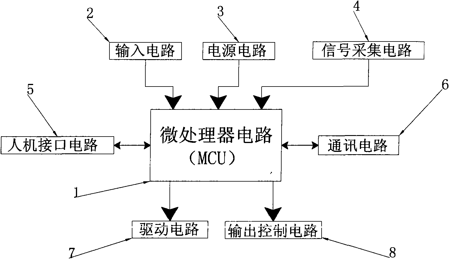
[0030] refer to figure 1 , which is a functional block diagram of the protection circuit of the present invention.

[0031] As shown in the figure: the signal acquisition circuit 4 converts the signal on the secondary side of the current transformer into a voltage signal after sampling, and sends it to the microprocessor circuit 1 after filtering and amplifying; the input circuit 2 detects the auxiliary signal of the control and protection switch and sends it to the microprocessor circuit 1; the drive circuit 7 is controlled by the microprocessor circuit 1 to drive the release, and pushes the control and protection switch to act; the output control circuit 8 is controlled by the microprocessor circuit 1 to send an alarm signal, and controls the on-off of the control and protection switch ; The power circuit 3 converts the AC mains voltage into multiple DC low voltages to ensure the normal operation of each circuit; the man-machine interface circuit 5 includes a display circuit...


PUM


Abstract

The invention relates to a protective circuit of a control and protection switch. The circuit comprises: a microprocessor circuit, a signal acquiring circuit, a power supply circuit, an input circuit, a drive circuit, an output control circuit, a human-computer interface circuit and a communication circuit. The circuit has a plurality of protection functions such as overload, phase failure, underload, imbalance and the like, as well as the display function of nixie tubes and the communication function of field buses, and can form a digital control and protection switch capable of communicating together with the main body of the control and protection switch. The protective circuit of the control and protection switch adopts few elements, effectively realizes the protection, control, measurement and display functions of the control and protection switch by reasonable connection, and has communication function. The circuit is simple in connection and high in anti-interference performance, and has the advantages of small volume and high reliability when used in the control and protection switch.

Description

technical field [0001] The invention relates to a protection circuit for a control and protection switch, belonging to the technical field of low-voltage electrical appliances. Background technique [0002] Control and protection switch (CPS) is a new product of low-voltage electrical appliances. CPS realizes integrated, internally coordinated control and protection functions on a single structural product, and can replace circuit breakers (fuse), contactors, Overload (or overcurrent, phase failure) protection relays, starters, isolators and many other traditional discrete devices can be widely used in automated centralized control systems. The control and protection switch (CPS) has a variety of structural forms, such as contactor-based, isolating switch-based, circuit breaker-based, etc., but there are roughly three forms of realization of the protection part: using bimetallic strips, using Analog circuits, using digital circuits. [0003] Patent No. 01238478.X is a util...

Claims


Application Information

Patent Timeline
IPC IPC(8): H02H7/22H02H3/08G01R31/00G05B15/02
Inventor 郭其一黄世泽刘娜
Owner 浙江中凯科技股份有限公司
Why Eureka
Try Eureka