An energy saving device for lighting

An energy-saving device and a common technology, applied in the field of lighting, can solve the problems of short life of electronic ballasts, small power saving range, large harmonic content, etc., to reduce reactive power consumption, reduce leakage, and improve power quality Optimized effect

Inactive Publication Date: 2009-10-07
SHENZHEN KEWEITIAN ECO LIGHTING
View PDF0 Cites 1 Cited by
  • Summary
  • Abstract
  • Description
  • Claims
  • Application Information

AI Technical Summary

Problems solved by technology

[0003] For this reason, people invented electronic ballasts, but in actual use, electronic ballasts have a short service life, and some even have regular strobes and large harmonic content. Although they save electricity compared with magnetic ballasts, the magnitude of power saving Not big, so it is necessary to improve the existing fluorescent lamp lighting

Method used


Image

  • An energy saving device for lighting
  • An energy saving device for lighting
  • An energy saving device for lighting

Examples


Embodiment 1

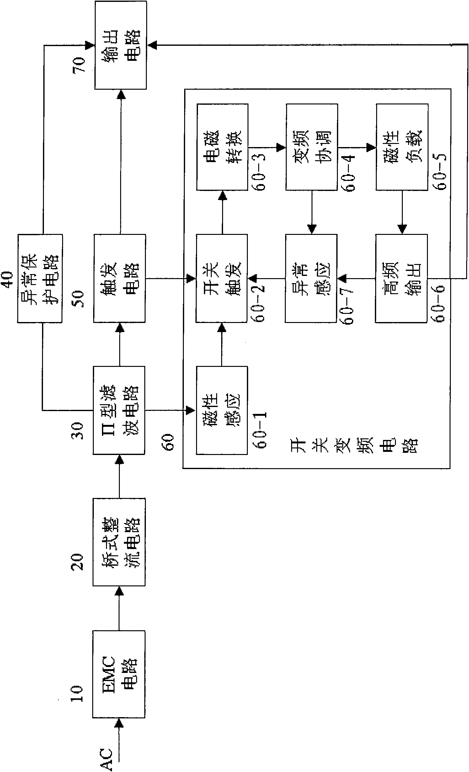
[0072] as attached figure 1 , 2 As shown, a lighting energy-saving device, the device includes a power saver JD, a lamp EL, and an inductance rectifier, the output circuit 70 of the power saver JD is connected to the lamp EL, and the input terminal of the power saver JD is connected to the power supply connected, or an inductance rectifier is connected between the input end of the power saver JD and the live wire L of the power supply;

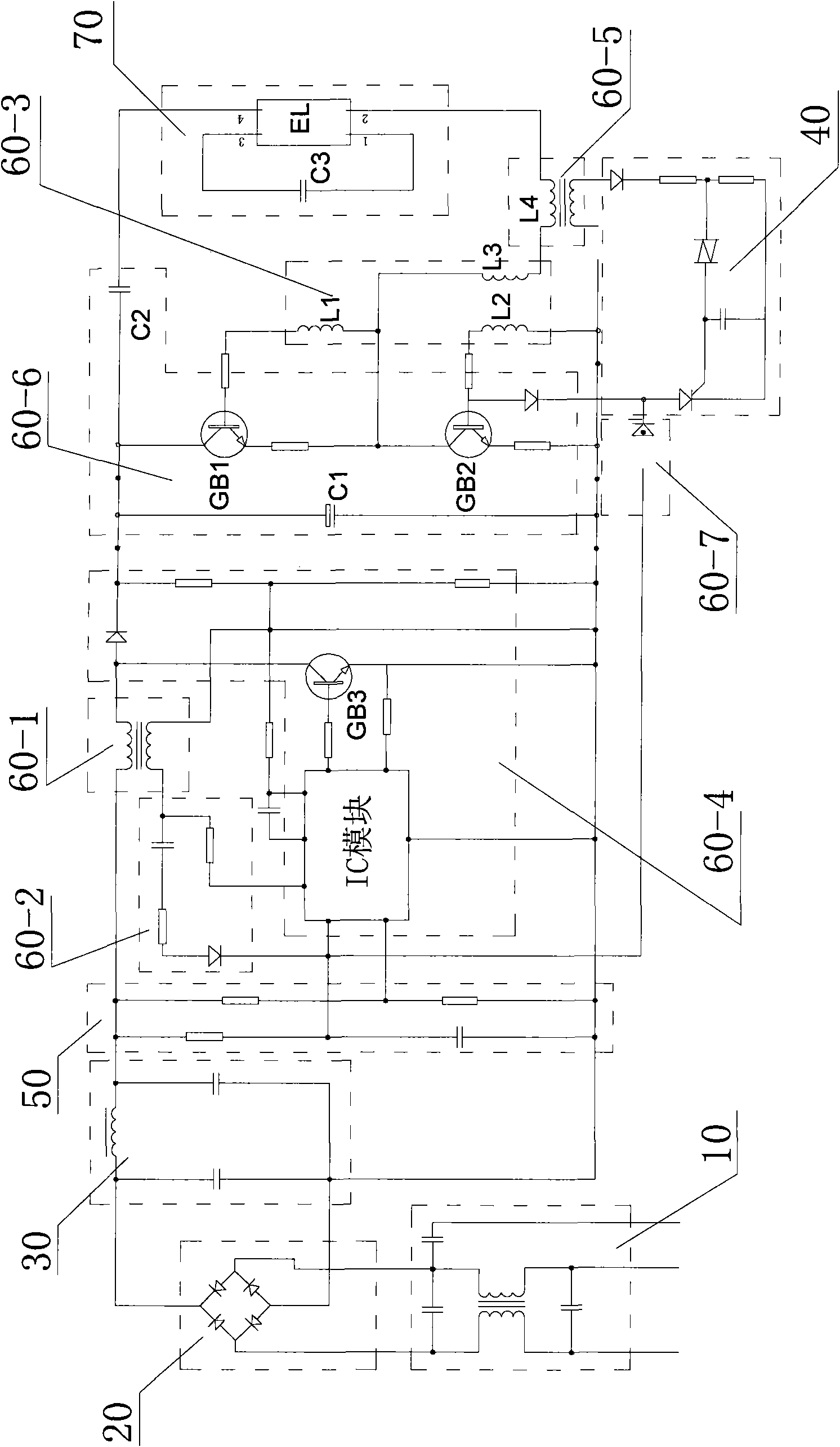
[0073] The power saver JD includes an electromagnetic compatibility circuit 10, a bridge rectifier circuit 20, a filter circuit 30, a trigger circuit 50, and an output circuit 70 connected in sequence, and an abnormal protection circuit 40 is connected between the filter circuit 30 and the output circuit 70 , the output circuit 70 is also connected to the high-frequency output sub-circuit 60-6 in the switch frequency conversion circuit 60;

[0074] The switch frequency conversion circuit 60 includes a magnetic induction sub-circuit 60-1, a s...

Embodiment 2

[0076] On the basis of Embodiment 1, the high-frequency output sub-circuit 60-6 passes through at least two transistors GB 1 、GB 2 The push-pull oscillation generates a high-frequency voltage, and the high-frequency voltage signal is transmitted to the magnetic ring type oscillation transformer 1 in the electromagnetic conversion sub-circuit 60-3 1 ~ l 3 , the choke coil l in the magnetic load sub-circuit 60-5 4 , the high-frequency voltage signal flows through the oscillation transformer l 1 ~ l 3 with choke coil l 4 After, through the DC blocking capacitor C 2 and start capacitor C 3 Provide high-frequency operating voltage for the lamp EL.

Embodiment 3

[0078] Such as image 3 As shown, on the basis of Embodiment 1, a circuit A is that a lamp EL is connected to the output circuit of the power saver JD, and the input end of the power saver JD is connected to the power line.


PUM


Abstract

The present invention relates to illuminating lamps. Concretely speaking, the invention is an energy saving device for lighting. This device comprises energy saver, lighting tube and inductive rectifier. The output circuit of the energy saver is connected to the lighting tube. The input end of the energy saver is connected to power source, or an inductive rectifier is connected between the input end of the energy saver and the live wire of the power source; the energy saver comprises EMC circuit, bridge rectifier circuit, filter circuit, trigger circuit and output circuit that are connected one by one. The connection between the filter circuit and the output circuit has an abnormal protection circuit. The output circuit is also connected to the high frequency output sub-circuit in the switch converter circuit. This device may obviously raise the illuminating brightness of the lighting tube and maximally increase the luminous efficiency or luminous flux of the lighting tube by above 50%, while lower power consumption by 50%-70% and reduce the harmonic content in circuits.

Description

technical field [0001] The invention relates to an illuminating lamp, in particular to an illuminating energy-saving device. Background technique [0002] After the invention of fluorescent tubes, the use of magnetic ballasts and white light tubes for lighting has occupied a considerable period of time in the field of lighting, so that in people's daily life and work, most of the places where fluorescent tubes are used for lighting are used The way the magnetic ballast is matched with the lamp tube. The lamp tube of this lighting system has low luminous efficiency, high power consumption, and low power factor. Especially when the circuit voltage is low, it is easy to produce stroboscopic flicker visible to the naked eye, which greatly harms people's eyes. [0003] For this reason, people invented electronic ballasts, but in actual use, electronic ballasts have a short service life, and some even have regular strobes and large harmonic content. Although they save electricity...

Claims


Application Information

Patent Timeline
Patent Type & Authority Applications(China)
IPC IPC(8): H05B41/295
Inventor 江新毅谢东谢锐
Owner SHENZHEN KEWEITIAN ECO LIGHTING
Why Eureka
Try Eureka