Aerial Cable Climbing Robot Clamping Mechanism

An overhead cable and clamping mechanism technology, applied in the field of robots, can solve the problems of low efficiency, poor adaptability, complex clamping structure, etc., and achieve the effect of wide application range, high clamping efficiency and compact structure

Inactive Publication Date: 2011-12-21
昆山市工业技术研究院有限责任公司
View PDF0 Cites 3 Cited by
  • Summary
  • Abstract
  • Description
  • Claims
  • Application Information

AI Technical Summary

Problems solved by technology

[0004] In order to overcome the shortcomings of the existing overhead cable climbing robots, such as complex clamping structure, low efficiency, and poor adaptability, the purpose of the present invention is to provide an overhead cable with compact structure, low energy consumption, fast and reliable clamping and releasing The clamping mechanism of the climbing robot can assist the cable climbing robot to achieve reliable walking on the overhead cable

Method used


Image

  • Aerial Cable Climbing Robot Clamping Mechanism
  • Aerial Cable Climbing Robot Clamping Mechanism
  • Aerial Cable Climbing Robot Clamping Mechanism

Examples


Embodiment 1

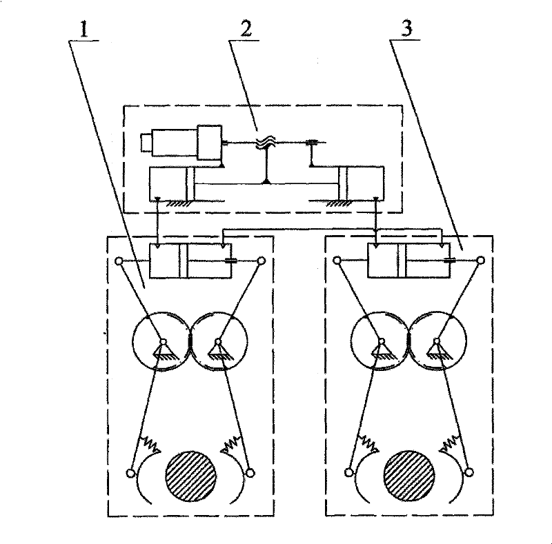
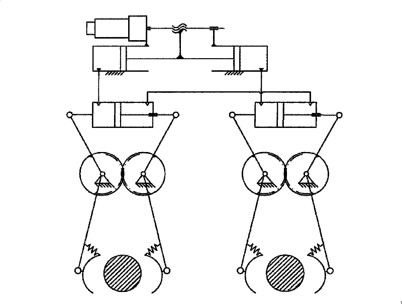
[0023] figure 1 Structural schematic diagram of Embodiment 1 of the clamping mechanism of the overhead cable climbing robot of the present invention; figure 2 It is a schematic diagram of the structure when the left clamping mechanism is clamped and the right clamping mechanism is released according to Embodiment 1 of the present invention.

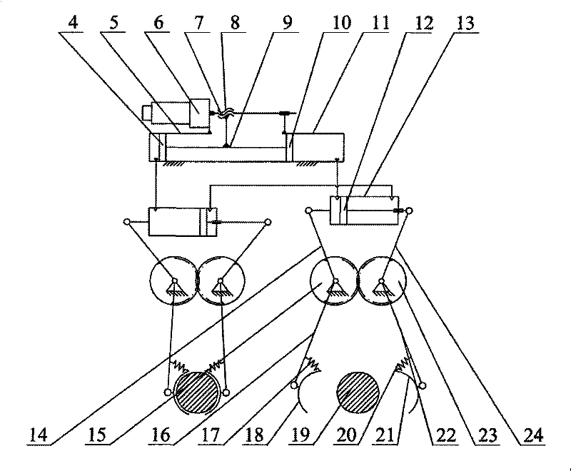
[0024] Such as figure 1 , 2 As shown, the clamping mechanism of the aerial cable climbing robot of the present invention includes a left clamping mechanism 1 , a power generating device 2 and a right clamping mechanism 3 . Wherein: the power generating device 2 includes a servo motor assembly 6, a lead screw 7, a screw nut 8, a push rod 9, a left power hydraulic cylinder 5, a left piston 4, a right power hydraulic cylinder 11, and a right piston 10. Wherein: the output shaft of the servo motor assembly 6 is connected with the lead screw 7, and the screw nut 8 moves on the lead screw 7 to cooperate with the lead screw 7. Screw nut 8 i...

Embodiment 2

[0031] Figure 6 It is a structural schematic diagram of Embodiment 2 of the present invention, such as Figure 6As shown, the overall structure of this embodiment is the same as that of Embodiment 1, the difference is that the power generating device 2' of this embodiment is a combination of a servo motor assembly and a bidirectional quantitative pump, the output shaft of the servo motor assembly is connected to a bidirectional quantitative pump, and the bidirectional quantitative The two outlets of the pump are respectively connected to the non-push rod chambers of the drive hydraulic cylinders of the left and right clamping mechanisms. The rotation of the servo motor is converted into the flow of hydraulic oil through a two-way quantitative pump, thereby driving the clamping mechanism to complete the clamping and releasing actions, and its working principle is the same as that of Embodiment 1.


PUM


Abstract

The invention relates to a clamping mechanism for an aerial cable climbing robot, which is characterized in that the left clamping mechanism and the right clamping mechanism have the same structure, respectively include a driving hydraulic cylinder, a piston rod, a left clamp, and a right clamp, and the left drive connecting rod is hinged on the On the driving hydraulic cylinder, the right driving connecting rod is hinged on the piston rod, and the other ends of the left driving connecting rod and the right driving connecting rod are fixedly connected to the left gear and the right gear respectively, and the left gear and the right gear are meshed. The right gear is also fixedly connected with a left clamping link and a right clamping link respectively, and the left clamp and the right clamp are respectively hinged at the ends of the left clamping link and the right clamping link, and are respectively connected to the On the left clamping link and the right clamping link; the power generating device is respectively connected to the drive hydraulic cylinder of the left and right clamping mechanisms of the left clamping mechanism without a push rod cavity, and the drive of the left and right clamping mechanisms The push rod chambers of the hydraulic cylinders are connected. The invention has the advantages of compact structure, saving driving motor, simple control and low energy consumption.

Description

technical field [0001] The invention relates to a robot mechanism, in particular to a clamping mechanism of a robot for walking along an overhead cable and overcoming obstacles, and belongs to the technical field of robots. Background technique [0002] At present, the operation and maintenance of overhead high-voltage transmission lines basically adopts the method of manual inspection, which is difficult, dangerous and labor-intensive. If the transmission line inspection robot is used to inspect the line, it can reduce the operation and maintenance cost of the high-voltage line, improve the efficiency of the inspection operation, and ensure the quality of line maintenance. [0003] The literature shows that the current overhead cable mobile robot mostly adopts a double-arm structure, and when encountering obstacles, it adopts the method of alternately taking off the line and hanging the line to achieve crossing. Therefore, the process of crossing obstacles can be divided in...

Claims


Application Information

Patent Timeline
Patent Type & Authority Patents(China)
IPC IPC(8): B62D57/02B25J15/00B25J13/00
Inventor 王鲁单程胜张建伟刘飞许少强王臻
Owner 昆山市工业技术研究院有限责任公司
Why Eureka
Try Eureka