Heat exchanger for flat heat pipe

A heat pipe heat exchanger, flat technology, applied in the field of flat heat pipe heat exchanger, to achieve the effect of improving heat exchange efficiency, small wind resistance, and energy saving

Inactive Publication Date: 2009-10-14
苏州森光换热器有限公司
View PDF1 Cites 8 Cited by
  • Summary
  • Abstract
  • Description
  • Claims
  • Application Information

AI Technical Summary

Problems solved by technology

[0008] The purpose of the present invention is to design a flat heat pipe heat exchanger to solve the technical problems

Method used


Image

  • Heat exchanger for flat heat pipe
  • Heat exchanger for flat heat pipe
  • Heat exchanger for flat heat pipe

Examples


Embodiment

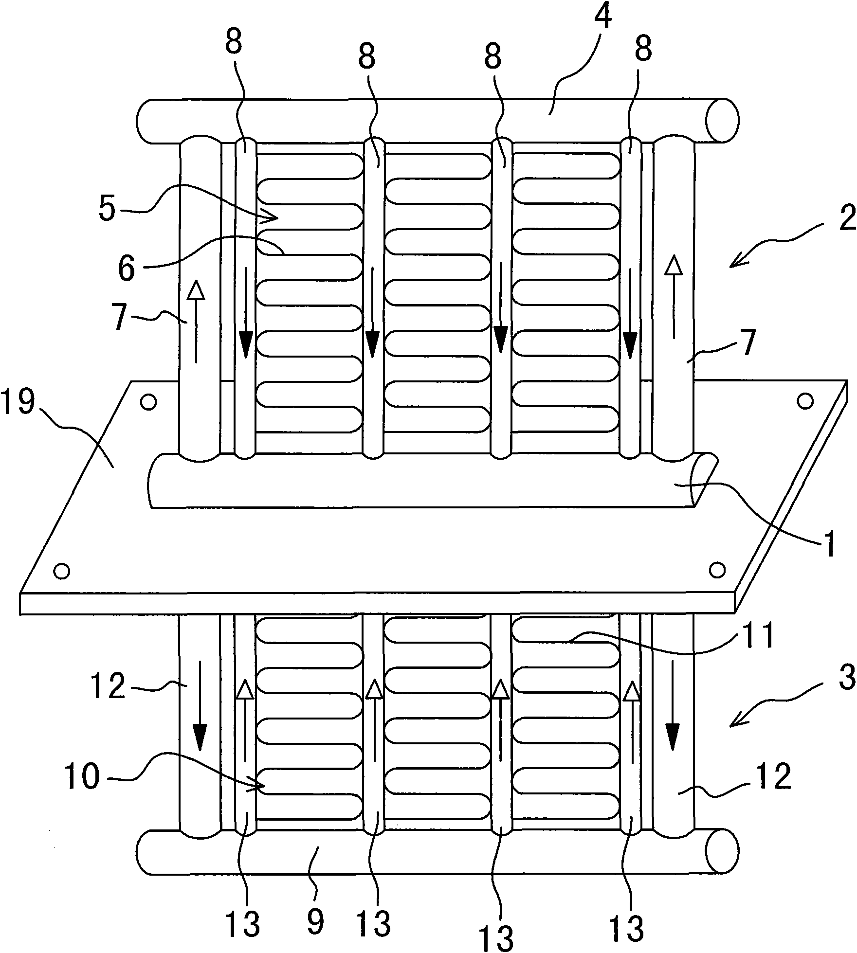
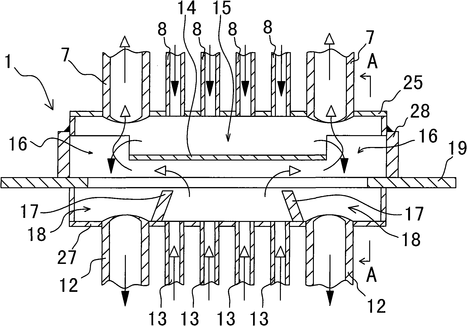
[0032] Example: see attached figure 2 ~ attached Figure 4 As shown, a flat heat pipe heat exchanger includes an intermediate gas-liquid separation chamber 1 , a condensation unit 2 located on the upper side of the intermediate gas-liquid separation chamber 1 , and an evaporation unit 3 located on the lower side of the intermediate gas-liquid separation chamber 1 .

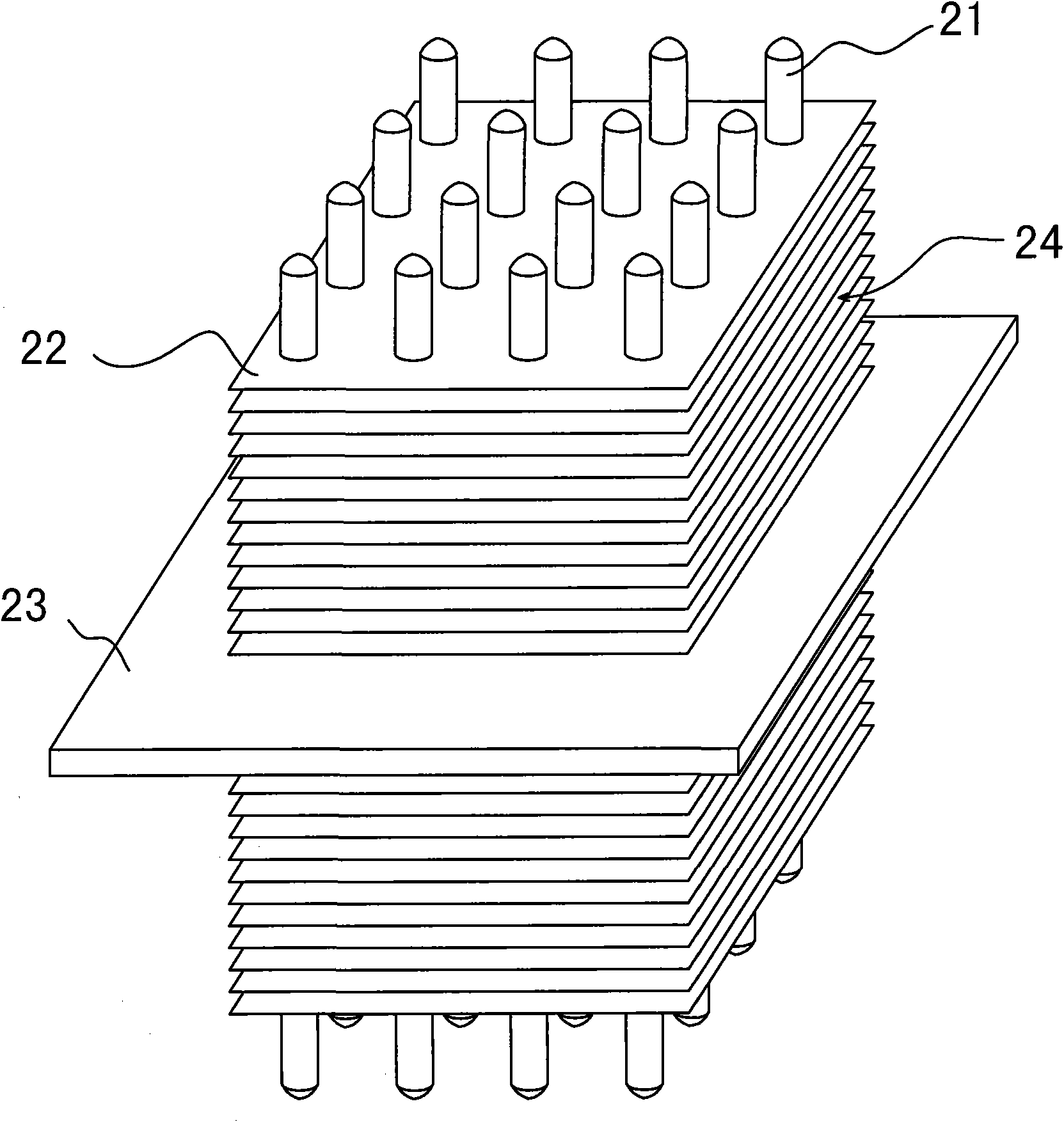
[0033] The condensing unit 2 is composed of a gas collecting pipe 4, a condensing flat tube group 5, a heat exchange fin 6 and two gas delivery pipes 7, and the gas collecting pipe 4 is arranged on the upper side of the middle gas-liquid separation chamber 1 in parallel; the condensing The flat tube group 5 is composed of a plurality of metal flat tubes 8 formed in a row and vertically connected between the gas collecting pipe 4 and the top of the intermediate gas-liquid separation chamber 1 (four in the figure). The heat exchange fins 6 are connected between the relatively flat surfaces to form a cold-end multi...


PUM


Abstract

The invention relates to a heat exchanger for a flat heat pipe, which is characterized in that the heat exchanger consists of a middle gas-liquid separation chamber, a condensation unit and an evaporation unit; the condensation unit consists of a gas collecting pipe, a condensation flat pipe group, a heat exchange plate and a gas conveying pipe; the condensation flat pipe group consists of a plurality of metal flat pipes which are connected between the gas collecting pipe and the top part of the middle gas-liquid separation chamber; the evaporation unit consists of a liquid collecting pipe, an evaporation flat pipe group, the heat exchange plate and a liquid conveying pipe; transverse baffle plates are arranged in the middle gas-liquid separation chamber and corresponding to the lower parts of pipe ends of all the metal flat pipes of the condensation flat pipe group, thereby forming a liquid guide channel by separation in the middle gas-liquid separation chamber; the periphery of the pipe end of the liquid conveying pipe arranged at the bottom part in the middle gas-liquid separation chamber is separated by a vertical baffle plate for forming a liquid storage cavity; a channel port of the liquid guide channel and the liquid storage cavity are relatively arranged at the upper and the lower parts; the condensation unit and the evaporation unit are communicated by the middle gas-liquid separation chamber and sealed to the outside as a whole, and working medium liquid is filled therein. The heat exchanger is a heat pipe structure as a whole, the packaging is more convenient, liquid and gas are further parallel, and the heat exchange efficiency is high.

Description

technical field [0001] The invention relates to a heat exchanger, in particular to a flat heat pipe heat exchanger. The flat heat pipe heat exchanger is especially suitable for cooling and heat dissipation in confined spaces such as outdoor electric power, communication or electrical control cabinets, and for energy-saving ventilation in places where air conditioners are used. Background technique [0002] Control cabinets are widely used in electric power, communication or electrical industries. In order to prevent moisture, dust, and harmful gases from entering the cabinet, the cabinet is usually closed to the outside. During operation, the temperature in the cabinet will increase due to the heat emitted by the components in the cabinet itself or the outdoor sunlight. If the heat is not dissipated in time, it will inevitably affect the normal operation of the components in the cabinet. Therefore, special heat exchangers need to be equipped in the power, communication or el...

Claims


Application Information

Patent Timeline
IPC IPC(8): F28D15/02F28F21/08F28F9/02F28F3/02
CPCF28D15/0266
Inventor 李建明
Owner 苏州森光换热器有限公司
Why Eureka
Try Eureka