Method, system and device realizing message transmission in Ethernet passive optical network (EPON)

A passive optical network and message forwarding technology, applied in the field of optical communication, can solve the problems of complex logic implementation, inability to measure distance and DBA technology, and inconvenient implementation, and achieve the effect of simple logic implementation

Inactive Publication Date: 2009-10-14
HUAWEI TECH CO LTD
View PDF0 Cites 9 Cited by
  • Summary
  • Abstract
  • Description
  • Claims
  • Application Information

AI Technical Summary

Problems solved by technology

However, in the prior art, 1G EPON OLT can only perform ranging and DBA technology for uplink messages from 1GEPON ONU, but cannot perform ranging and DBA technology for uplink messages from 10G ONU, and 10G EPON OLT can only perform ranging and DBA technology for uplink messages from 10G EPON ONU performs ranging and DBA technology on the upstream message, but cannot perform ranging and DBA technology on the upstream message from 1G ONU, so when 1G ONU and 10G ONU send upstream messages, there will be conflicts, so a The public DBA module coordinates th...

Method used


Image

  • Method, system and device realizing message transmission in Ethernet passive optical network (EPON)
  • Method, system and device realizing message transmission in Ethernet passive optical network (EPON)
  • Method, system and device realizing message transmission in Ethernet passive optical network (EPON)

Examples


Embodiment 1

[0046] Embodiment 1. The detailed processing flow of this embodiment is divided into descriptions in the uplink and downlink directions.

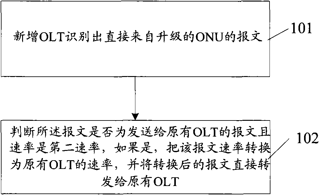
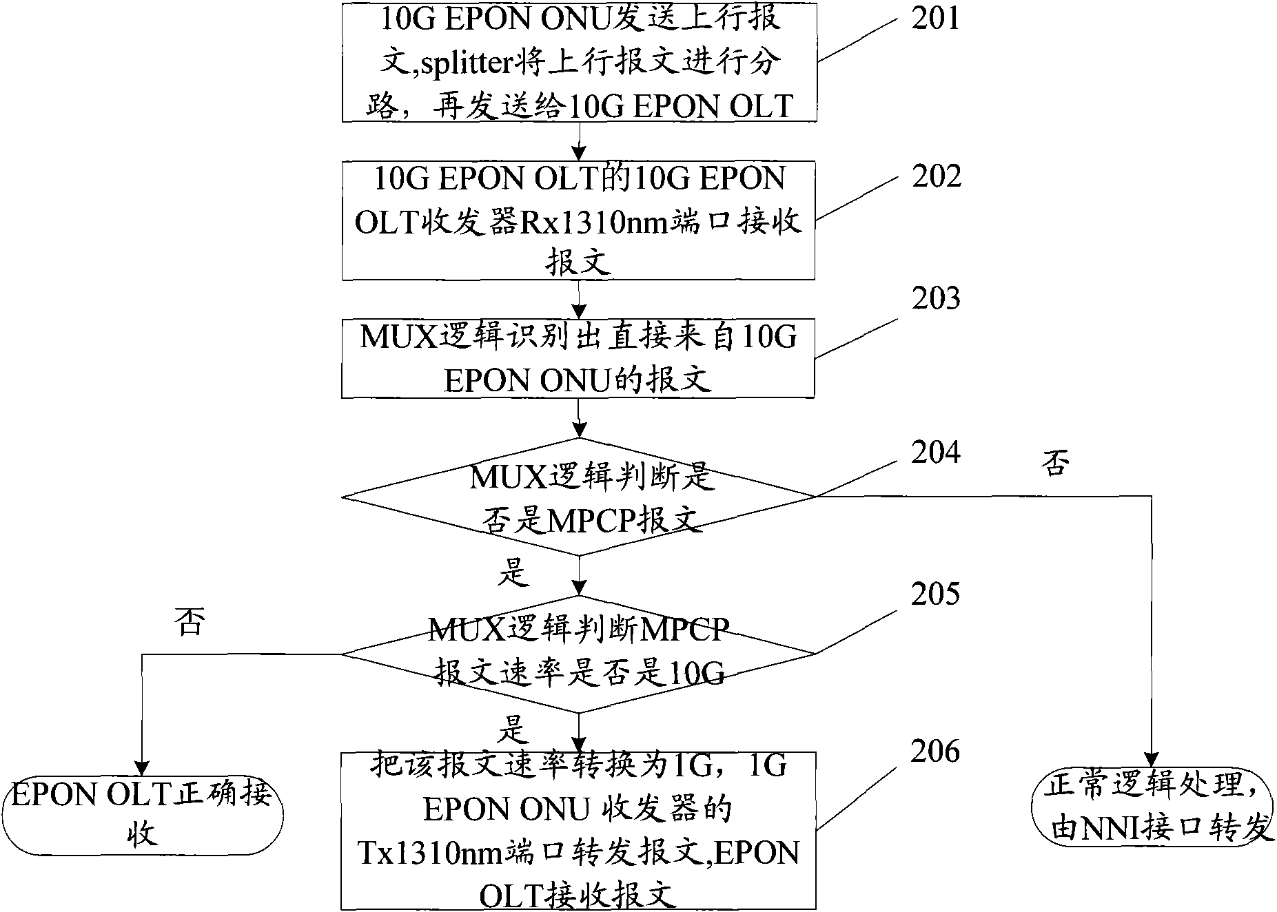
[0047] For the uplink direction, see figure 2 , implementing the method provided by the embodiment of the present invention includes:

[0048] Step 101: the newly added OLT recognizes the message directly from the upgraded ONU;

[0049] Step 102: judging whether the message is sent to the original OLT and the rate is the second rate, if so, converting the rate of the message to the rate of the original OLT, and directly forwarding the converted message to the original OLT.

[0050] Those skilled in the art know that because only one user is allowed to transmit at a given moment in the uplink direction, in order to avoid conflicts between different users, a multi-point control protocol (MPCP, Multi-point controlprotocol) is adopted. Through the MPCP protocol, multiple ONUs share the OLT . In addition, the MPCP protocol enables ranging a...

Embodiment 2

[0089]Embodiment 2, the idea of ​​this embodiment is the same as that of method embodiment 1, the difference is that in this embodiment, the newly added OLT in the uplink direction does not directly forward the message that needs to be forwarded to the original EPON OLT, but sends the message first to the splitter, and then forwarded to the original EPON OLT; the downstream direction has also been changed accordingly. The detailed processing flow is also described for the uplink and downlink directions.

[0090] For the uplink direction, see Image 6 , implementing the method provided by the embodiment of the present invention includes:

[0091] Step 501: the newly added OLT recognizes the message directly from the upgraded ONU;

[0092] Step 502: Determine whether the message is sent to the original OLT and the rate is the second rate, if so, convert the rate of the message to the rate of the original OLT, and send the converted message first To the splitter, and then forw...


PUM


Abstract

The invention discloses a method, a system and a device realizing message transmission in the Ethernet passive optical network (EPON). The method is as follows: a 10 G optical line terminal (OLT) is additionally arranged in the EPON to be used as a transit station of a 10 G EPON optical network unit (ONU) and a 1G EPON OLT transit station to recognize the up message directly coming from a 10 G EPON ONU, judge whether the up message is the multiple-point control protocol (MPCP) message, and only transmit the MPCP message to a 1G EPON OLT. The system comprises an original EPON OLT, an additionally-arranged 10 G EPON OLT and a 10 G EPON ONU. The device comprises a logic unit, a 10 G EPON OLT transceiver and a 1 G EPON ONU transceiver. The invention can guarantee that no conflict exists in the up direction without additionally arranging a unified scheduling module.

Description

technical field [0001] The invention relates to the field of optical communication, in particular to a method, system and device for realizing message forwarding in an Ethernet Passive Optical Network (EPON, Ethernet Passive Optical Network). Background technique [0002] EPON can provide full-service, high-speed fiber-to-the-home (FTTH, Fiber To The Home) optical access network, which includes optical line terminal (OLT, Optical Line Terminal), optical network unit (ONU, Optical Network Unit), optical Splitter. [0003] In EPON, the transmission direction from OLT to ONU is the downlink direction, which is transmitted by Time Division Multiplexing (TDM, Time Division Multiplex). OLT continuously broadcasts information to ONUs, and each ONU selects its own data to receive. The transmission direction from the ONU to the OLT is the uplink direction, and the transmission is performed in a Time Division Multiple Access (TDMA, Time Division Multiple Access) manner. [0004] Wit...

Claims


Application Information

Patent Timeline
IPC IPC(8): H04L12/56H04L12/28H04L29/06H04L12/811
Inventor 赵泉波冯志山
Owner HUAWEI TECH CO LTD
Why Eureka
Try Eureka