Automobile braking system

An automobile braking system and the technology of the braking system are applied in the field of automobile braking system based on motor drive, which can solve the problems such as failure to monitor in real time, unable to find mechanical devices, inconvenient installation, etc., and achieve simple structure and less accessories. , construct a simple effect

Active Publication Date: 2011-08-10
CHERY AUTOMOBILE CO LTD
View PDF1 Cites 0 Cited by
  • Summary
  • Abstract
  • Description
  • Claims
  • Application Information

AI Technical Summary

Problems solved by technology

However, no matter the traditional hydraulic brake or the above-mentioned technology, there are defects such as complex structure, inconvenient installation, high price, and failure to be monitored in real time. hint of braking effect

Method used


Image

  • Automobile braking system
  • Automobile braking system
  • Automobile braking system

Examples


Embodiment Construction

[0010] The invention also emphatically considers safety guarantee measures such as motor blockage, motor damage, and mechanical self-locking, thereby improving the safety factor of the braking system. The braking system includes the following mechanisms:

[0011] Embedded control system consists of hardware and corresponding software.

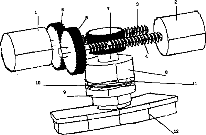
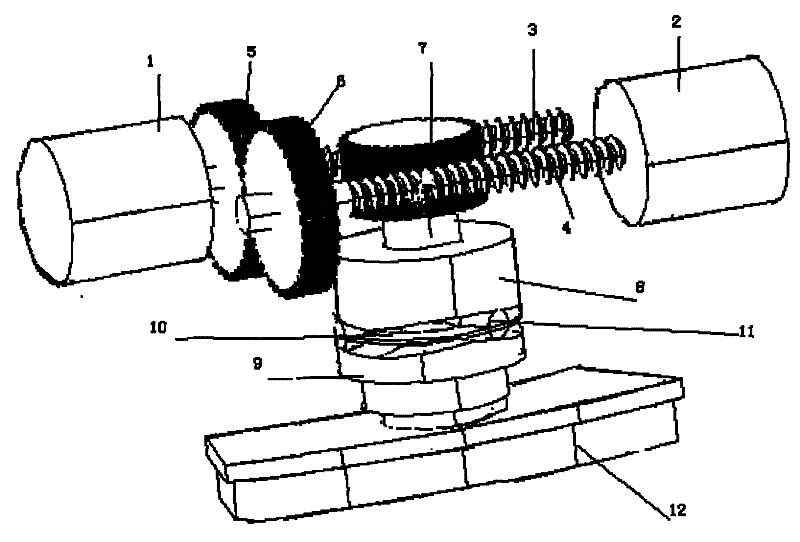
[0012] Drive motor 1 and drive motor 2 are fixedly connected with screw mandrel 3 and screw mandrel 4 respectively, as figure 1 . During the running of the vehicle, the drive motors 1 and 2 receive control signals from the embedded control system at any time.

[0013] The gear 5 and the gear 6 are respectively fixed on the screw mandrel 3 and the screw mandrel 4 and engage with each other, wherein the screw mandrel 3 and the screw mandrel 4 engage the push rod gear 7 front and back together. When the motors 1 and 2 rotate, the screw rods 3 and 4 jointly drive the push rod gear 7 to rotate, because the relative positions of the screw rods 3 a...


PUM


Abstract

The invention discloses an automobile braking system, which comprises a mechanical transmission mechanism and a brake pushrod group mechanism, wherein the mechanical transmission mechanism comprises two drive motors (1, 2), two screw mandrels (5, 6) and an shaft lever gear (7). Two drive motors are fixedly connected with the two screw mandrels respectively, and the two screw mandrels are meshed with the shaft lever gear (7); the brake pushrod group mechanism comprises an upper brake pushrod (8), a lower brake pushrod (9), an isolator (10) between the upper brake pushrod and the lower brake pushrod and a roller set (11); and the shaft lever gear (7) is fixedly connected with the upper brake pushrod (8). The automobile braking system has simple structure, eliminates the traditional hydrauliccontrol and represents the convenience of operation in respect of installation and maintenance. Furthermore, the braking system has good universality and is suitable for all automobile types in principle, in particular for automobiles using new energy, thus being capable of realizing pure electric automobiles in the true sense.

Description

technical field [0001] The invention relates to an automobile brake system, in particular to an automobile brake system driven by a motor. Background technique [0002] At present, most vehicle brake systems at home and abroad are still based on hydraulic control of mechanical pressure to achieve the purpose of braking. In the known technology, technical materials similar to the technical effect of the present invention are: "linear braking type" braking system (CN101039826), as disclosed in it, under the linear working state, brake is produced by pedal pressure simulator The displacement is processed by the corresponding electronic control unit to obtain the output braking torque. Through this technology, we can realize that the braking signal is collected by the embedded controller and processed accordingly. However, no matter the traditional hydraulic brake or the above-mentioned technology, there are defects such as complex structure, inconvenient installation, high pr...

Claims


Application Information

Patent Timeline
Patent Type & Authority Patents(China)
IPC IPC(8): B60T11/08B60T13/74H02K7/10
Inventor 朱得亚胡滨周勇
Owner CHERY AUTOMOBILE CO LTD
Why Eureka
Try Eureka