Compressor driving device of bus with air conditioner
An automotive compressor and transmission technology, which is applied to machines/engines, supporting machines, mechanical equipment, etc., can solve the problems of the compressor bracket being easily deformed by force, the passengers are uncomfortable and not very adaptable, etc., and the structure is simple, Improved comfort and reduced manufacturing costs
- Summary
- Abstract
- Description
- Claims
- Application Information
AI Technical Summary
Problems solved by technology
Method used
Image

Examples
Embodiment Construction
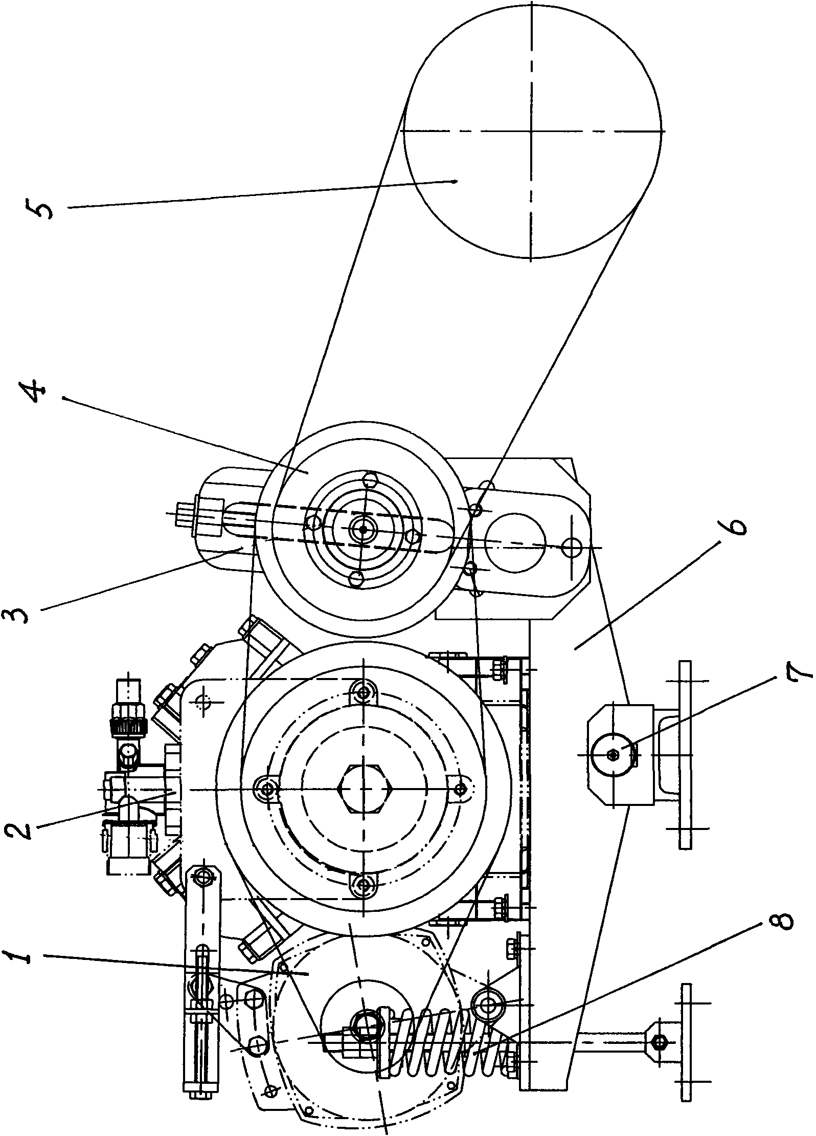
[0034] Below in conjunction with accompanying drawing, provide the specific embodiment of the present invention bus air-conditioning car compressor transmission device.
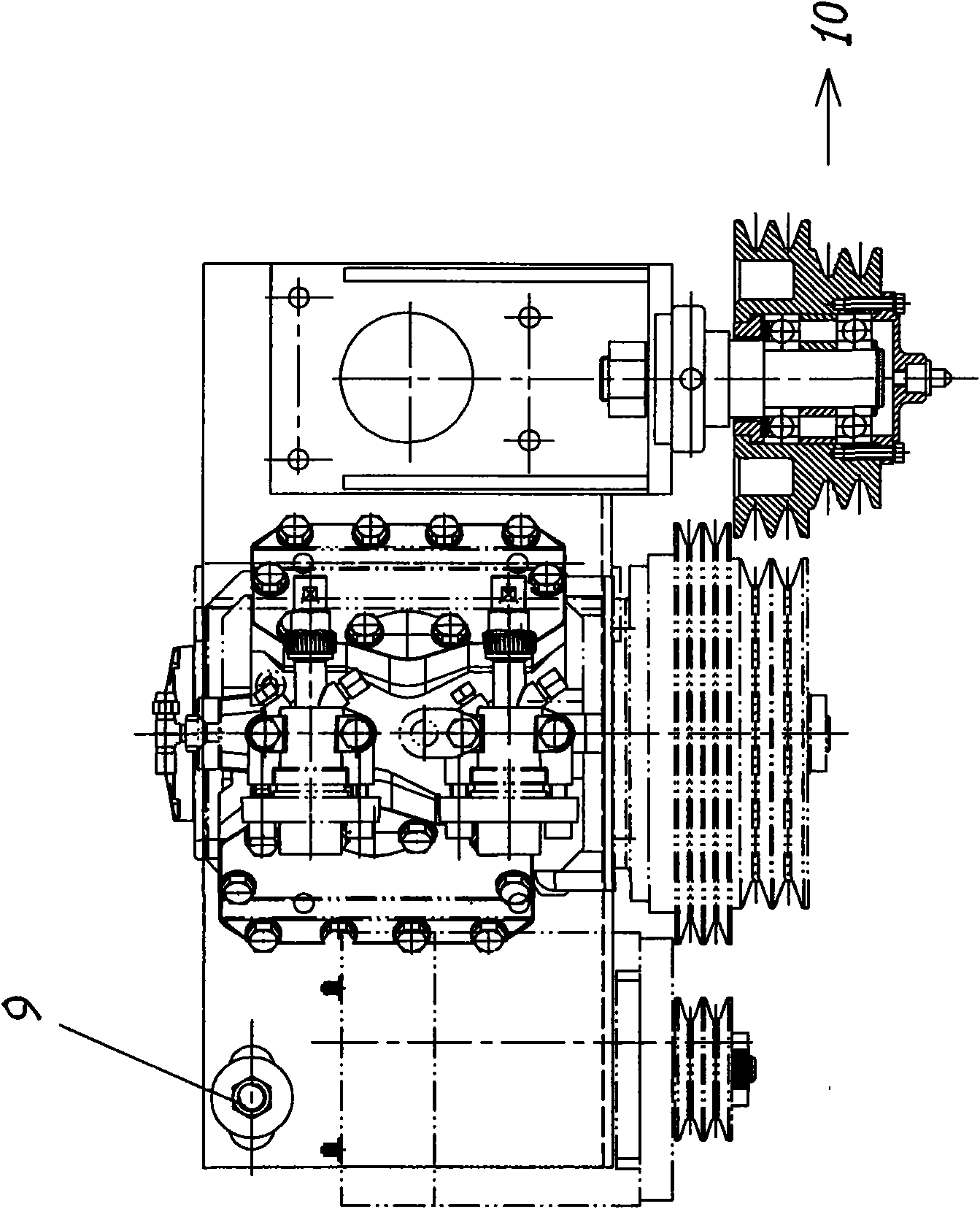
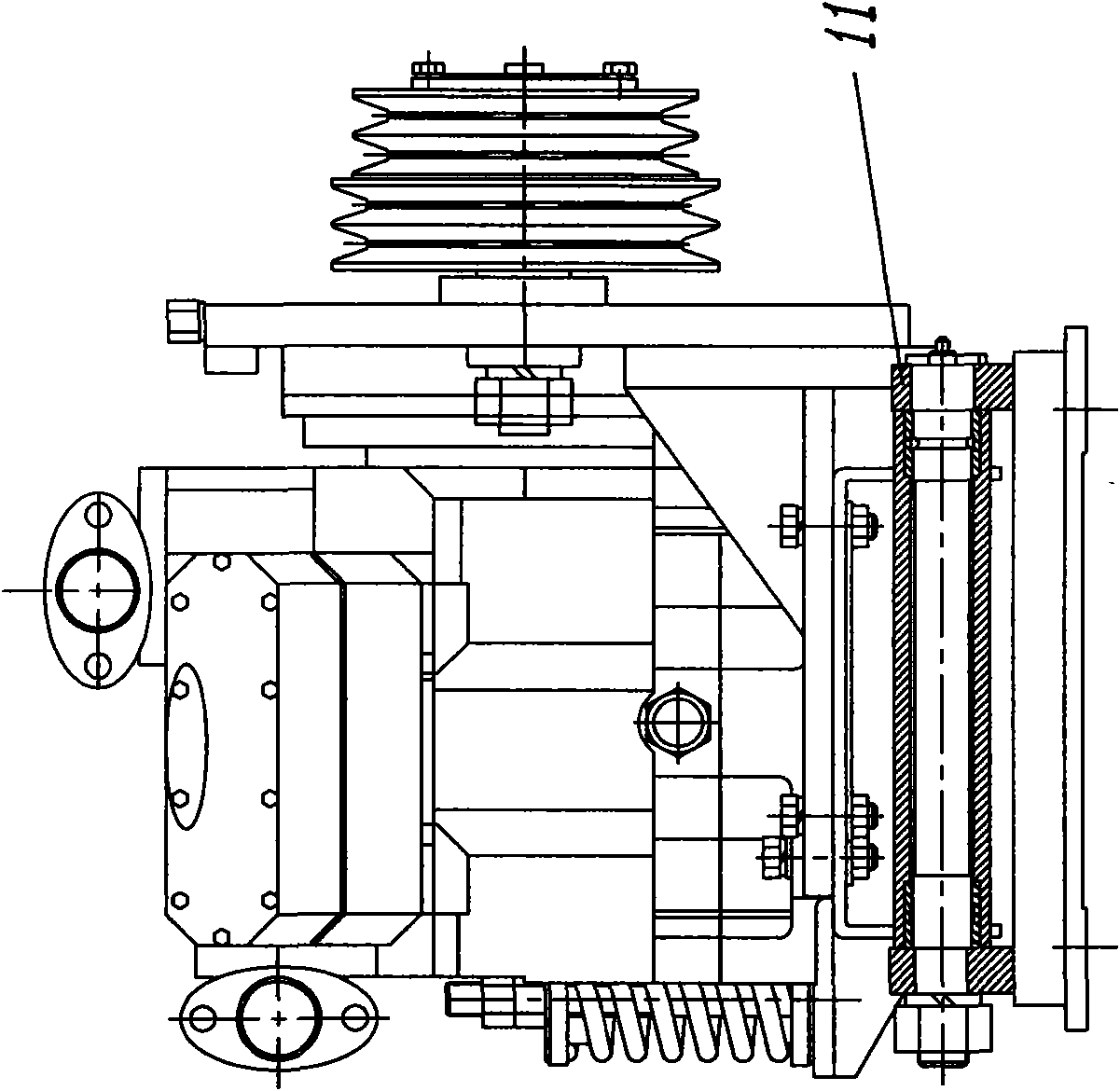
[0035] See attached Figure 4 . A compressor transmission device for a bus air-conditioning car, including a generator 1, a compressor 2, an engine drive wheel 5, a compressor bracket 6, a core shaft 7, and a compression spring 8, and the generator 1 and compressor 2 are arranged on the compressor bracket 6 Above, adopt the flexible installation structure that the supporting seat of compressor bracket 6 can swing around the mandrel 7, the present invention no longer arranges speed change mechanism 3 and transition wheel 4, and engine drive wheel 5 directly drives compressor 2, for this reason, engine and compression The drive wheel of the machine must match.
[0036] Since the rated speed of the engine matched with the air-conditioned bus in my country ranges from 2000rpm, 2100rpm, 2200rpm, 2300rpm, 2400rpm...
PUM
 Abstract
Description
Claims
Application Information