
Device for continuously removing optical fiber coating and winding bare fiber

A coating and optical fiber technology is applied in the field of continuous removal of optical fiber coating for fiber optic gyroscopes and bare fiber winding devices, which can solve the problems of inability to meet the requirements of volume and weight miniaturization, and achieve the effect of volume reduction

Inactive Publication Date: 2011-07-20
ZHEJIANG UNIV
View PDF0 Cites 0 Cited by
  • Summary
  • Abstract
  • Description
  • Claims
  • Application Information

AI Technical Summary

Problems solved by technology

Although the existing optical gyroscope has been greatly reduced in terms of weight and volume compared with the mechanical type, it still cannot meet the stringent miniaturization requirements of the new generation inertial navigation system for volume and weight.

Method used


Image

  • Device for continuously removing optical fiber coating and winding bare fiber
  • Device for continuously removing optical fiber coating and winding bare fiber
  • Device for continuously removing optical fiber coating and winding bare fiber

Examples


Embodiment Construction

[0015] The present invention will be further described below in conjunction with the accompanying drawings and embodiments.

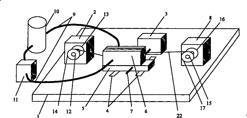
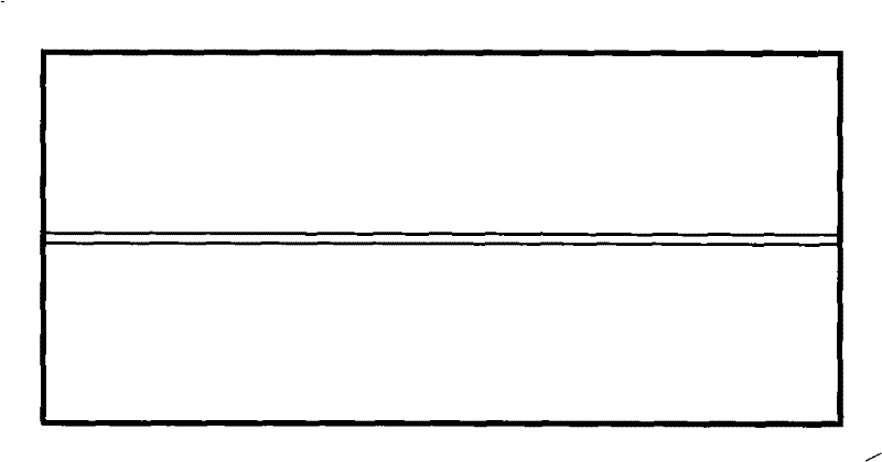
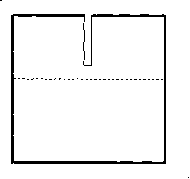
[0016] Such as figure 1 , 2, and 3, the continuous removal of the optical fiber coating layer and the bare fiber winding device for the optical fiber gyroscope are: the first motor 2, the second motor 3, the parallel guide rail 4, and the third motor 8 are installed in sequence on the base 1, A slide block 5 and a dissolving chamber 6 are successively installed on the parallel guide rail 4, and the dissolving chamber 6 is connected to the liquid container 10 and the liquid pump 11 through two liquid conduits 9; the first rotating shaft 12 is installed on the front side of the first motor 2, and the first The rotating shaft 12 is driven to rotate by the first motor 2, and the first baffle plate 13 and the backup ring 14 are installed on the first rotating shaft 12; the second rotating shaft 7 with thread is installed on the front side of the second motor...


PUM


Abstract

The invention discloses a device for continuously removing an optical fiber coating and winding a bare fiber for an optical fiber gyro. A first motor, a second motor, a parallel guide and a third motor are arranged on a base in turn; the parallel guide is provided with a sliding block and a solution chamber; the solution chamber is connected with a liquid pump through two liquid conduits and a fluid container; the front lateral surface of the first motor is provided with a first rotating shaft, and the first rotating shaft is driven to rotate by the first motor and is provided with a first baffle and a preparation ring; the front lateral surface of the second motor is provided with a second rotating shaft with threads, wherein the second rotating shaft is driven to rotate by the second motor and passes through the middle part of the sliding block, and the solution chamber is internally provided with two pulleys and solution; and the front lateral surface of the third motor is providedwith a third rotating shaft which is driven to rotate by the third motor and is provided with a second baffle and an annual shelf to be winded. The device is used for continuously removing the opticalfiber coating and winding the bare fiber into an optical-fiber ring.

Description

technical field [0001] The invention relates to an optical fiber winding device, in particular to a device for continuously removing an optical fiber coating layer for an optical fiber gyroscope and winding a bare fiber. Background technique [0002] As the key angle sensor of the new generation inertial navigation system, the fiber optic gyroscope has attracted much attention and developed rapidly because of its unparalleled anti-shock, anti-interference, high precision, and large dynamics. Although the existing optical gyroscope has been greatly reduced in terms of weight and volume compared with the mechanical type, it still cannot meet the stringent miniaturization requirements of the new generation inertial navigation system for volume and weight. Therefore, the miniature fiber optic gyroscope came into being, which can well meet the development trend of miniaturization of the inertial navigation system without reducing the performance index. To make a miniature fiber ...

Claims


Application Information

Patent Timeline
Patent Type & Authority Patents(China)
IPC IPC(8): G01C19/72G02B6/02
Inventor 盛芳佘玄舒晓武刘承
Owner ZHEJIANG UNIV
Learn More