Wind tunnel heat exchange system

A technology of heat exchange system and heating system, which is applied in the direction of measuring devices, instruments, aerodynamic tests, etc., and can solve the problems of poor control accuracy and narrow adjustment range of total air temperature in wind tunnel tests

Pending Publication Date: 2020-03-24
JIANGSU YONGSHENG AIR CONDITIONER
View PDF0 Cites 3 Cited by
  • Summary
  • Abstract
  • Description
  • Claims
  • Application Information

AI Technical Summary

Problems solved by technology

Traditionally, changing the cooling water flow through the frequency conversion pump has a small change in the total heat transfer coefficient, and the change in the hea...

Method used


Image

  • Wind tunnel heat exchange system

Examples


Embodiment 1

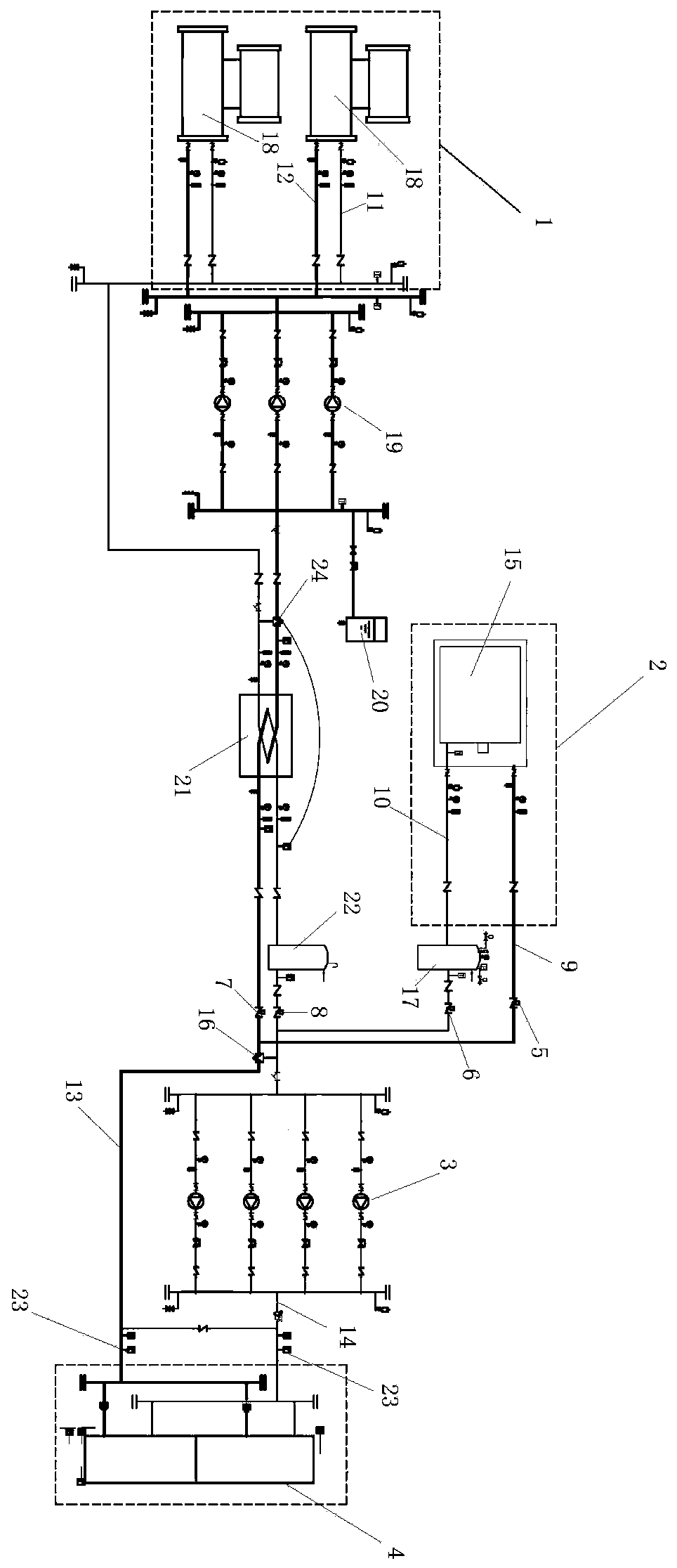
[0027] Such as figure 1 The wind tunnel heat exchange system shown includes a heating system 1, a cooling system 2, a water supply pump 3 and a wind tunnel heat exchanger 4. The hot liquid supply pipeline 9 and the hot liquid return pipeline 10 of the heating system 1 are respectively provided with a second An electric valve 5 and a second electric valve 6, the cold liquid supply pipeline 11 and the cold return liquid pipeline 12 of the refrigeration system 2 are respectively provided with a third electric valve 7 and a fourth electric valve 8, and the hot liquid supply pipe 9 is connected to the cold supply pipe. After the liquid pipeline 11 meets, it forms a liquid supply pipeline 13 and is connected to the liquid inlet of the wind tunnel heat exchanger 4. The water outlet is connected, the liquid supply pipeline 13 is connected with the liquid return pipeline 14 through the electric three-way valve 16, the water supply pump 3 is set on the liquid return pipeline 12, and the...

Embodiment 2

[0029] Such as figure 1 The wind tunnel heat exchange system shown includes a heating system 1, a cooling system 2, a water supply pump 3 and a wind tunnel heat exchanger 4. The hot liquid supply pipeline 9 and the hot liquid return pipeline 10 of the heating system 1 are respectively provided with a second An electric valve 5 and a second electric valve 6, the cold liquid supply pipeline 11 and the cold return liquid pipeline 12 of the refrigeration system 2 are respectively provided with a third electric valve 7 and a fourth electric valve 8, and the hot liquid supply pipe 9 is connected to the cold supply pipe. After the liquid pipeline 11 meets, it forms a liquid supply pipeline 13 and is connected to the liquid inlet of the wind tunnel heat exchanger 4. The water outlet is connected, the liquid supply pipeline 13 is connected with the liquid return pipeline 14 through the electric three-way valve 16, the water supply pump 3 is set on the liquid return pipeline 12, and the...

Embodiment 3

[0036] Such as figure 1 The wind tunnel heat exchange system shown includes a heating system 1, a cooling system 2, a water supply pump 3 and a wind tunnel heat exchanger 4. The hot liquid supply pipeline 9 and the hot liquid return pipeline 10 of the heating system 1 are respectively provided with a second An electric valve 5 and a second electric valve 6, the cold liquid supply pipeline 11 and the cold return liquid pipeline 12 of the refrigeration system 2 are respectively provided with a third electric valve 7 and a fourth electric valve 8, and the hot liquid supply pipe 9 is connected to the cold supply pipe. After the liquid pipeline 11 meets, it forms a liquid supply pipeline 13 and is connected to the liquid inlet of the wind tunnel heat exchanger 4. The water outlet is connected, the liquid supply pipeline 13 is connected with the liquid return pipeline 14 through the electric three-way valve 16, the water supply pump 3 is set on the liquid return pipeline 12, and the...


PUM


Abstract

The invention provides a wind tunnel heat exchange system. The system comprises a heating system, a refrigerating system, a water supply pump and a wind tunnel heat exchanger, a first electric valve and a second electric valve are respectively arranged on a hot liquid supply pipeline and a hot liquid return pipeline of the heating system; a third electric valve and a fourth electric valve are respectively arranged on a cold liquid supply pipeline and a cold liquid return pipeline of the refrigerating system; the hot liquid supply pipeline and the cold liquid supply pipeline are intersected toform a liquid supply pipeline which is connected with a liquid inlet of the wind tunnel heat exchanger; the hot liquid return pipeline and the cold liquid return pipeline intersect to form a liquid return pipeline to be connected with a water outlet of the wind tunnel heat exchanger, the liquid supply pipeline is connected with the liquid return pipeline through the electric three-way valve, the water supply pump is arranged on the liquid return pipeline, the water-water heat exchanger is arranged between the cold liquid supply pipeline and the liquid return pipeline, and the normal pressure storage tank is arranged on the liquid return pipeline. The system has the beneficial effects that PID adjustment can be carried out according to the temperature detected by the sensor, and the liquidsupply temperature and precision of the heat exchanger of the test hall meet the target requirements.

Description

technical field [0001] The invention relates to the field of wind tunnel heat exchange systems, and more specifically relates to a wind tunnel heat exchange system. Background technique [0002] The connected transonic wind tunnel needs to be cooled or heated to keep the total temperature of the test airflow stable. The external cooling water flows through the heat exchanger installed in the heat exchange section of the wind tunnel to exchange heat with the wind tunnel airflow. Traditionally, changing the cooling water flow through the frequency conversion pump has a small change in the total heat transfer coefficient, and the change in the heat transfer temperature difference is limited. As a result, the total air temperature adjustment range of the wind tunnel test is narrow and the control accuracy is poor. Contents of the invention [0003] The invention overcomes the deficiencies in the prior art and provides a wind tunnel heat exchange system. [0004] The purpose o...

Claims


Application Information

Patent Timeline
IPC IPC(8): G01M9/04
CPCG01M9/04
Inventor 周涛戴亚东郁兵冯卫石滨泉陈俊
Owner JIANGSU YONGSHENG AIR CONDITIONER
Why Eureka
Try Eureka