Catalytic reduction type de-nitrification reactor of circulating fluidized bed

A denitration reactor and circulating fluidized bed technology, which is applied in chemical instruments and methods, separation methods, chemical/physical processes, etc., can solve the problem of catalysts easily coming out of the fluidized bed, etc., and reduce the floor space and investment cost. , improve the utilization rate, the effect of sufficient response

Inactive Publication Date: 2013-12-11
HENAN UNIV OF SCI & TECH
View PDF4 Cites 4 Cited by
  • Summary
  • Abstract
  • Description
  • Claims
  • Application Information

AI Technical Summary

Problems solved by technology

[0005] The purpose of the present invention is to provide a circulating fluidized bed catalytic reduction denitrification react

Method used


Image

  • Catalytic reduction type de-nitrification reactor of circulating fluidized bed
  • Catalytic reduction type de-nitrification reactor of circulating fluidized bed
  • Catalytic reduction type de-nitrification reactor of circulating fluidized bed

Examples


Embodiment 1

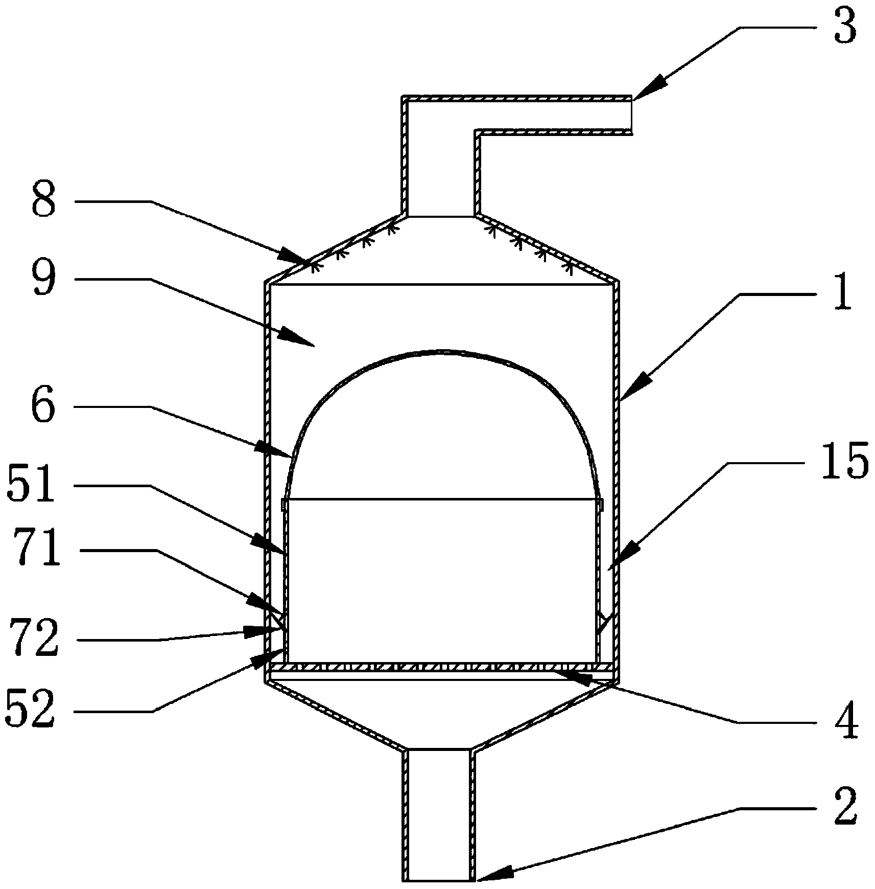
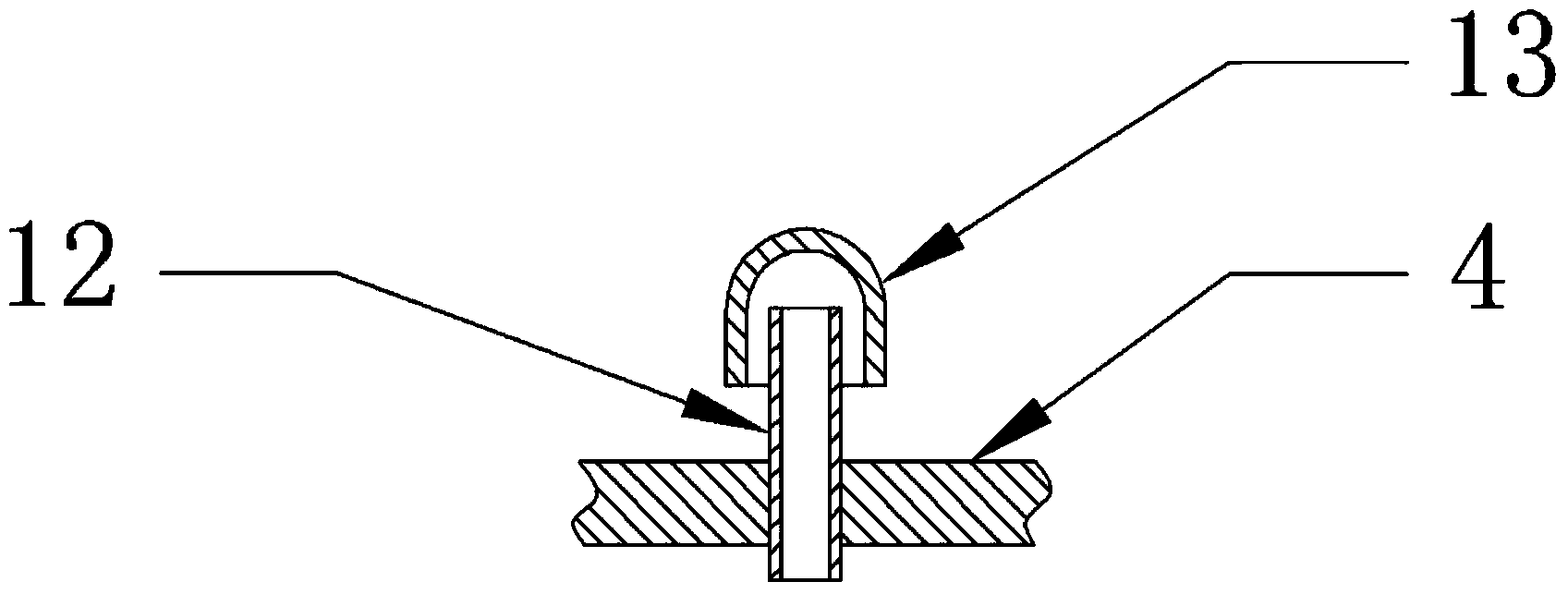
[0024] The circulating fluidized bed catalytic reduction method denitrification reactor of embodiment 1, such as figure 1 As shown, it includes a reactor shell 1 with a reactor cavity 9, the bottom and top of the reactor shell 1 are respectively provided with an inlet flue 2 and an outlet flue 3 communicating with the reactor cavity 9, the The lower part of the reactor inner cavity 9 is provided with an air distribution plate 4 with air distribution holes, and above the air distribution plate 4 in the reactor inner cavity 9, there is a wall closed with the top, and the lower part has a downward opening for intercepting The filter container of the catalyst, the container wall of the filter container is provided with filter holes; in this embodiment, the filter container is made of a support cylinder and a filter bag 6, and the support cylinder includes an upper support cylinder 51 and a The lower support cylinder 52, there is a return channel 15 for the catalyst to fall between...

Embodiment 2

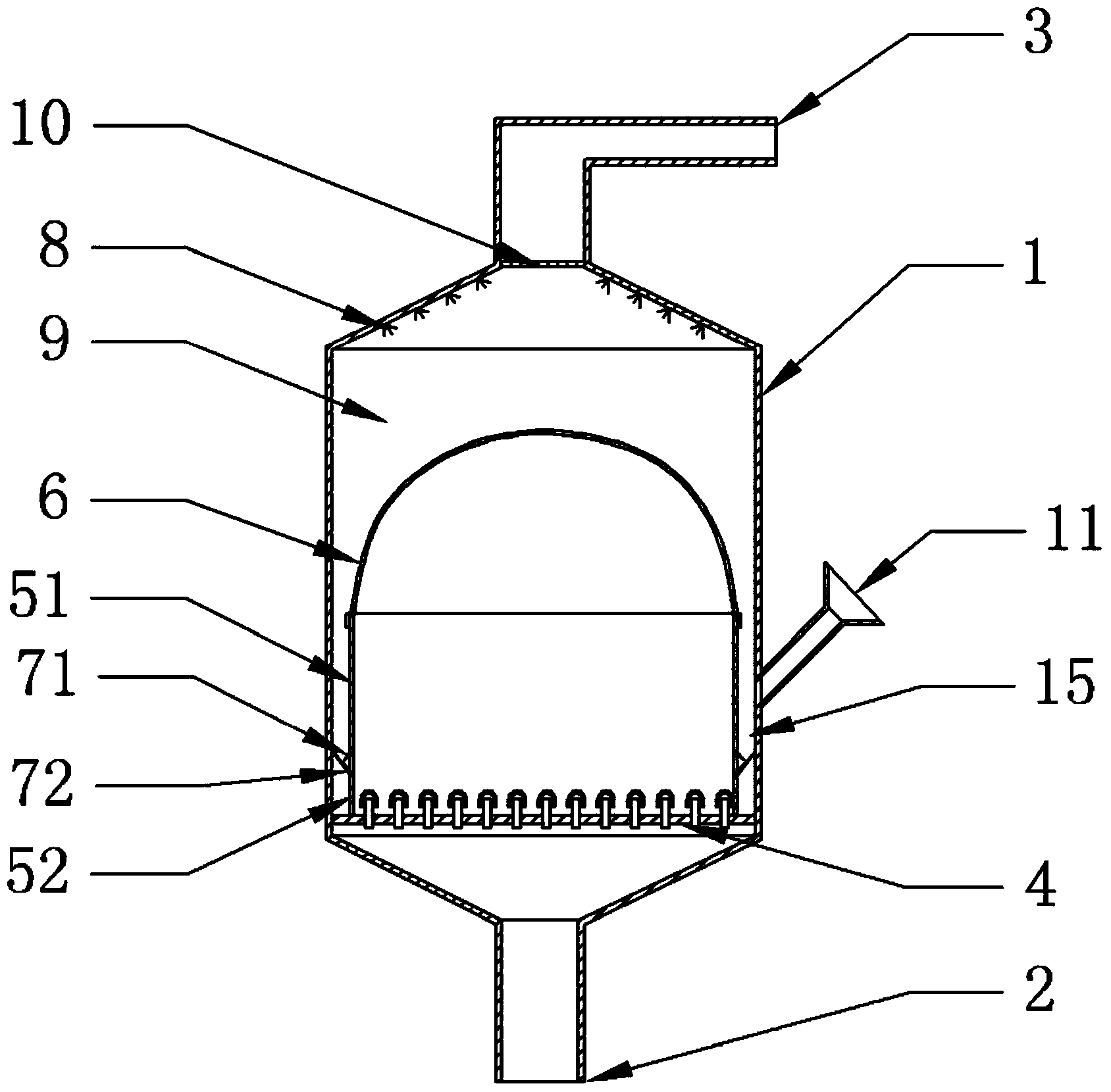
[0027] The circulating fluidized bed catalytic reduction method denitrification reactor of embodiment 2, such as figure 2 ,3 As shown, the difference from Example 1 is that a baffle plate 10 is provided at the place where the reactor inner chamber 9 communicates with the outlet flue 3, and the baffle plate 10 is a porous plate, and the aperture of the through hole on the baffle 10 is smaller than that of the filter container When the equipment is running, the catalyst removed from the fluidized bed rises with the flue gas, and is intercepted by the baffle plate and falls. The reactor shell 1 is provided with a feeding port 11 communicated with the reactor inner chamber 9, the feeding port 11 is located above the feeding port, during the operation of the equipment, the lost catalyst can be added through the feeding port 11, and the added The catalyst enters the return channel 15, and enters the filter container through the return port 7, so as to ensure that the amount of cata...

Embodiment 3

[0028] The circulating fluidized bed catalytic reduction method denitrification reactor of embodiment 3, such as Figure 4 As shown, the difference from Example 2 is that: the reactor inner cavity 9 is provided with a guide cover 16 above the filter container, the guide cover 16 is opened downward and has a middle part with the shielding plate 10. A cover structure with through holes arranged opposite to each other up and down. The cross section of the cover structure is in the shape of an "eight", and the lower edge of the guide cover 16 is located above the return channel 15. The inner surface of the guide cover 16 is provided with a denitration reactant adding device, and the denitrifying reactant adding device is an ammonia water nozzle 8 . The role of the guide cover 16 is to guide the catalyst intercepted by the baffle plate 10 or the inner wall of the reactor cavity 9 to the feed-back channel 15 .


PUM


Abstract

The invention discloses a catalytic reduction type de-nitrification reactor of a circulating fluidized bed. The catalytic reduction type de-nitrification reactor comprises a reactor housing with a reactor inner cavity, wherein the bottom and the top of the reactor housing are respectively provided with an inlet flue and an outlet flue; the lower part of the reactor inner cavity is provided with an air distribution plate with air distribution holes; a filtering container is arranged above the air distribution plate in the reactor inner cavity and is used for intercepting a catalyst; the periphery and the top of the filtering container are sealed; the lower part of the filtering container is provided with a downward opening; the container wall of the filtering container is provided with filtering holes; a material returning channel in which the catalyst drops is remained between the external surface of the container wall of the filtering container and the inner wall of the reactor inner cavity; material returning openings connected with the material returning channel are formed between an opening edge of an opening of the filtering container and the air distribution plate or formed in the container wall of the lower part of the filtering container. Through the de-nitrification reactor disclosed by the invention, the amount of the catalyst removed from the fluidized bed along with flue gas is greatly reduced, the catalyst can react in the de-nitrification reactor all the time, and the utilization rate of the catalyst is effectively increased.

Description

technical field [0001] The invention belongs to the technical field of flue gas denitrification, and in particular relates to a circulating fluidized bed catalytic reduction denitrification reactor. Background technique [0002] my country is a big country with coal and oil as the main primary energy sources. During the combustion of coal and oil, a large amount of nitrogen oxides (nitrate) will be produced, causing environmental pollution such as acid rain and photochemical smog, which seriously threatens people's health and continues to deteriorate our dependence. To survive in the environment, but also bring huge losses to the national economy. In recent years, the treatment of nitrogen oxides has become the focus of attention. At present, the flue gas denitrification method commonly used in China is selective redox method. [0003] The principle of Selective Catalytic Reduction (SCR) is that under the action of a catalyst, the reducing agent NH 3 At 290-400°C, NO and NO...

Claims


Application Information

Patent Timeline
IPC IPC(8): B01D53/90B01D53/56B01J8/24
Inventor 王学涛张兴宇焦叶凡屈成锐兰维娟刘春梅
Owner HENAN UNIV OF SCI & TECH
Why Eureka
Try Eureka