Strap-down magnetic inertia combination system

A combined system, magnetic inertial technology, applied in the field of navigation technology measurement, can solve the problems of increasing ineffective weight, complex system, sacrificing rudder resources, etc.

Inactive Publication Date: 2009-10-21
BEIJING INSTITUTE OF TECHNOLOGYGY +1
View PDF0 Cites 28 Cited by
  • Summary
  • Abstract
  • Description
  • Claims
  • Application Information

AI Technical Summary

Problems solved by technology

The disadvantage of this method is that the system is complex, the ineffective weight is increased, and part of the rudder resources are sacrificed
The United States is re...

Method used


Image

  • Strap-down magnetic inertia combination system
  • Strap-down magnetic inertia combination system
  • Strap-down magnetic inertia combination system

Examples


Embodiment Construction

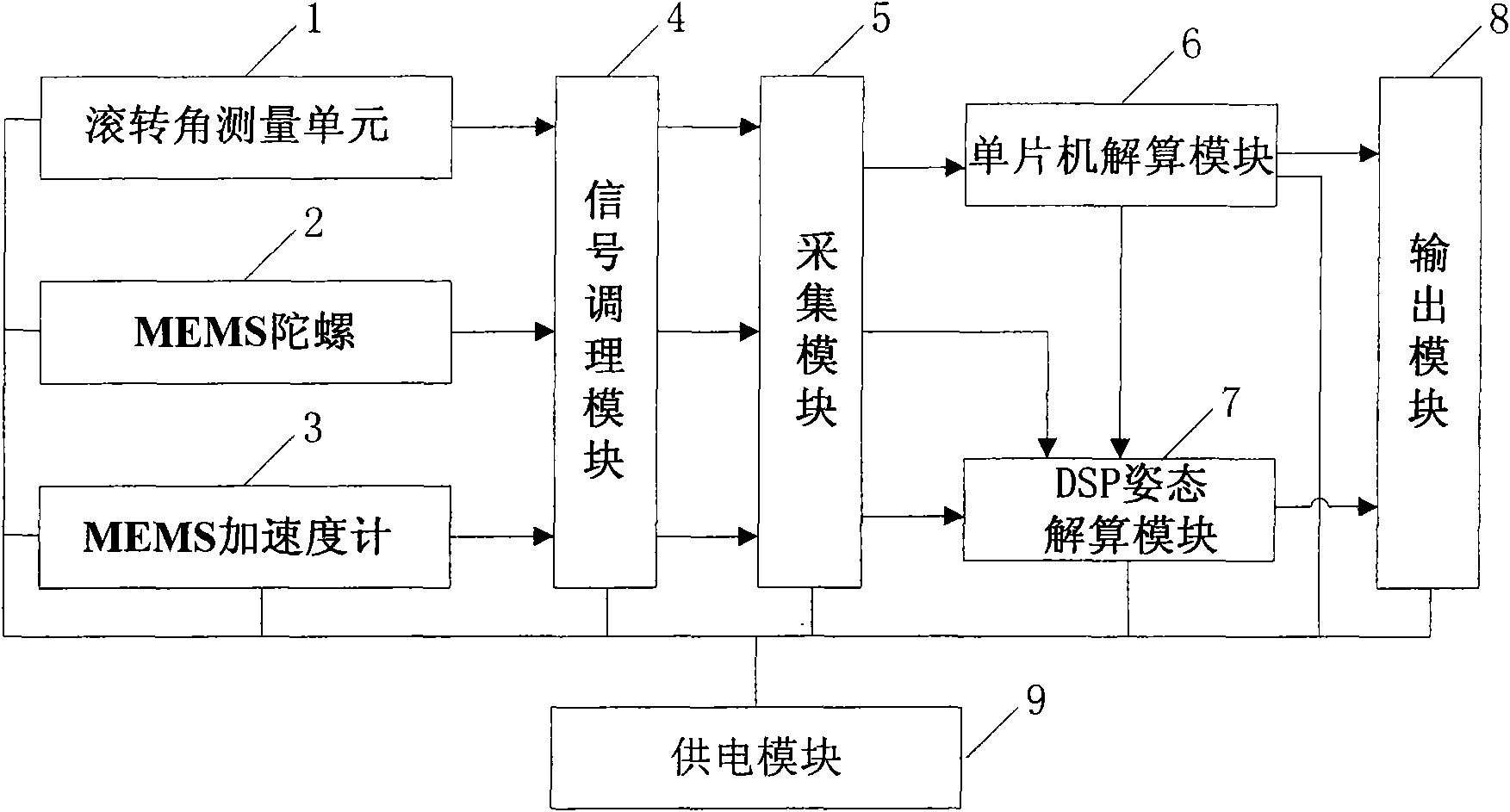
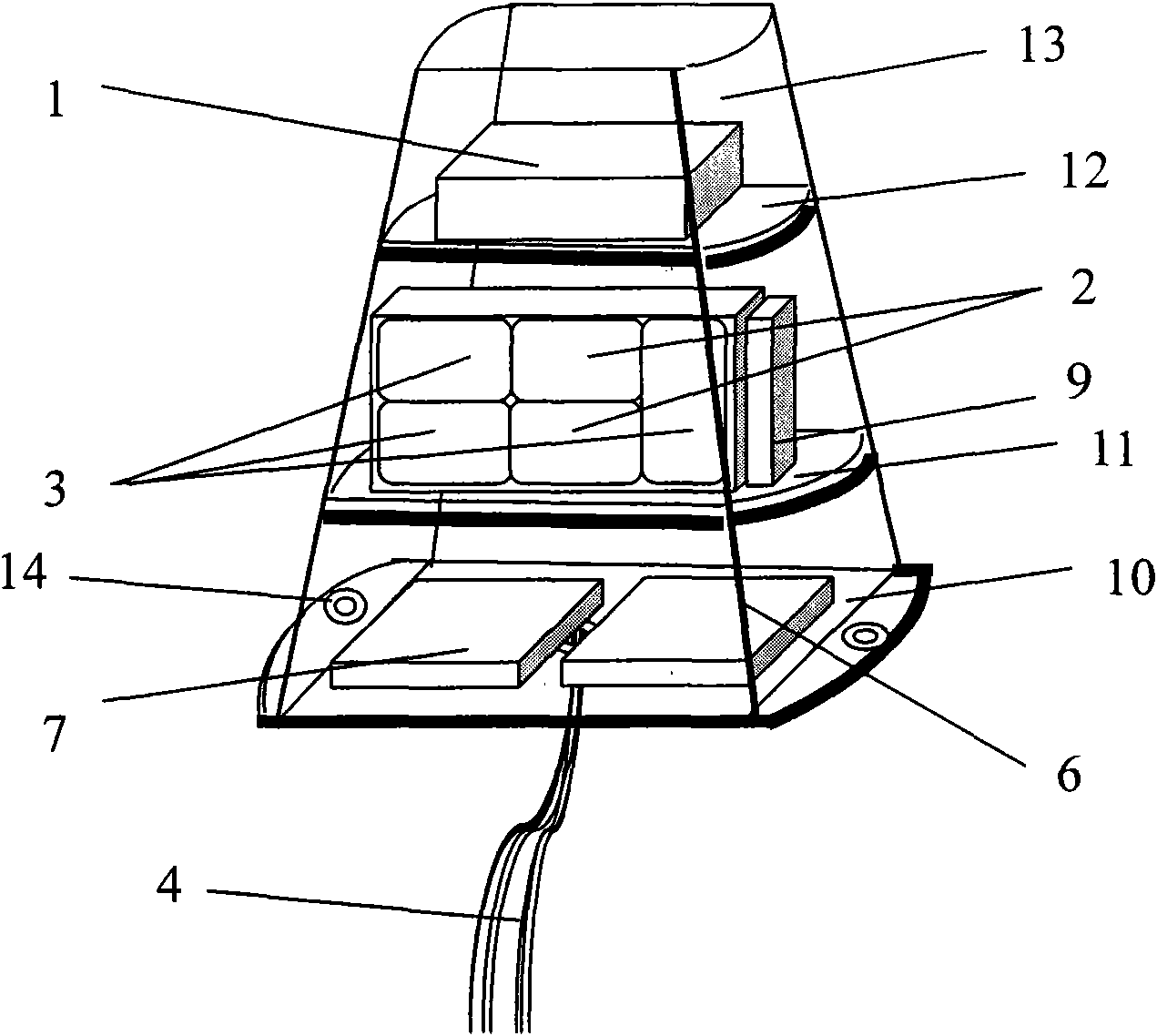
[0089] The magnetic-inertial combination system of the present invention is implemented according to the following technical scheme: it mainly consists of two uniaxial angular rate micro-machined gyroscopes, three micro-machined accelerometers, a two-axis geomagnetic roll angle measurement unit, a missile-borne computer and a power supply circuit It is directly fixed on the structural body in a strapdown manner. All components and MEMS sensors use solid chips, which are mounted on the board level through damping sheets in layers, and are potted in the housing with damping glue to form a whole. Workflow: Binding the shooting direction, local magnetic inclination, and magnetic declination of the rotating projectile. With the rotation of the projectile, the geomagnetic roll angle measurement unit obtains the magnetic signal of the sinusoidal change, and then calculates the roll of the main shaft according to these binding parameters. Turn angle and roll rate. The rates of the pi...


PUM


Abstract

The invention relates to a strap-down magnetic inertia combination system. In the system, a signal conditioning module filters and amplifies an angular rate signal and a sine signal; an acquisition module carries out analog/digital conversion for the angular rate signal and the sine signal conditioned by the signal conditioning module, sends the sine signal to a first resolving module, and outputs the angular rate signal to a second resolving module; according to the sine signal, the first resolving module resolves a roll angle gamma and roll angle rate omega x; according to the angular rate signal and the roll angle rate omega x, the second resolving module resolves an azimuth angle psi and a pitching angle theta; and an output module is used for outputting the roll angle gamma, the azimuth angle psi and the pitching angle theta. For the measurement of the roll angle rate, the system does not use the prior angular rate gyro, but directly uses a geomagnetic roll angle measuring unit to resolve the roll angle and the roll angle rate of a rotary bomb; and because the position of the roll angle can be directly acquired, the integral accumulated error brought by integral acquisition position quantity is avoided.

Description

technical field [0001] The invention belongs to the field of navigation technology measurement and relates to a strapdown magnetic-inertial combination system. Background technique [0002] The strapdown inertial navigation system has been maturely explored since the early 1960s. Especially in 1969, the strapdown inertial navigation system was used as an emergency backup device for the "Apollo"-13 lunar landing spacecraft. It played a decisive role in the successful guidance of the spacecraft to the orbit back to the earth, which became a milestone in the development of the strapdown inertial navigation system. Since the 1970s, great progress has been made in the technology of inertial sensors and inertial navigation systems, and various types of inertial sensors (such as laser gyroscopes, fiber optic gyroscopes, dynamic tuning gyroscopes, etc.) have been successfully developed, and obtained a wide range of applications. In terms of system technology, the strapdown inertia...

Claims


Application Information

Patent Timeline
IPC IPC(8): G01C21/12G01C21/06F42B15/01
Inventor 李兴城施国兴杨树兴苏中
Owner BEIJING INSTITUTE OF TECHNOLOGYGY
Why Eureka
Try Eureka