Backlight module and liquid crystal display device using same

A technology for liquid crystal display devices and backlight modules, which is applied to lighting devices, components of lighting devices, optics, etc., and can solve problems such as low utilization efficiency of light energy, inability to meet the uniform light output of light sources at the same time, and inability to manufacture thin display devices, etc.

Inactive Publication Date: 2009-10-21
INNOLUX CORP
View PDF0 Cites 9 Cited by
  • Summary
  • Abstract
  • Description
  • Claims
  • Application Information

AI Technical Summary

Problems solved by technology

However, for the side-lit backlight module 10 that alternately emits light on both sides, due to structural limitations, no matter how the dot distribution is designed, it is impossible to satisfy the light sources on both sides to achieve uniform light output at the same time, resulting in uneven bri

Method used


Image

  • Backlight module and liquid crystal display device using same
  • Backlight module and liquid crystal display device using same
  • Backlight module and liquid crystal display device using same

Examples


Embodiment 1

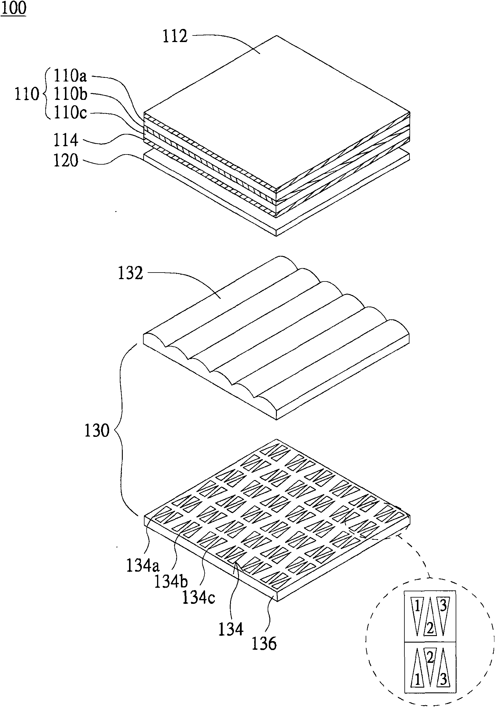
[0045] Please also refer to Figure 2A and Figure 2B , which respectively show an exploded perspective view and a side view of the liquid crystal display device of the first embodiment. The liquid crystal display device 100 includes a liquid crystal display panel 110 , an optical film 120 , a backlight module 130 and a power supply module (not shown). The upper polarizing film 112 and the lower polarizing film 114 are respectively attached to the upper surface and the lower surface of the liquid crystal display panel 110 . The liquid crystal display panel 110 includes a first substrate 110a, a liquid crystal layer 110b and a second substrate 110c, wherein the first substrate 110a is, for example, a color filter substrate, and the second substrate 110c is, for example, a thin film transistor substrate. The backlight module 130 is located under the liquid crystal display panel 110 , and the optical film 120 is located between the liquid crystal display panel 110 and the backl...

Embodiment 2

[0051] Please refer to image 3 , which shows a side view of the liquid crystal display device of the second embodiment. The main difference between the liquid crystal display device 200 of this embodiment and the liquid crystal display device 100 of the first embodiment is that the backlight module 230 includes a light source 234 and an optical switch element 233 . The rest of the elements that are the same as those in Embodiment 1 continue to use their symbols. The light source 234 is located on the substrate 236. In this embodiment, the substrate 236 is a back plate. The substrate 236 has a reflective layer 240 for reflecting the light source 234 to improve light energy utilization efficiency. The optical switch element 233 is located on the light source 234 , and the first light emitting unit 233 a and the second light emitting unit 233 b are evenly distributed on the optical switch element 233 . The light source 234 may be a light emitting diode (light emitting diode, L...


PUM


Abstract

The invention discloses a backlight module and a liquid crystal display device using the backlight module. The backlight module comprises a baseplate, a plurality of first light-emitting units, a plurality of second light-emitting units and optical modulation elements, wherein the first light-emitting units are evenly distributed on the baseplate, and the second light-emitting units are adjacent to the first light-emitting units and are evenly distributed on the baseplate. The optical modulation elements are positioned on the first light-emitting units and the second light-emitting units, and are used for controlling the first light-emitting units and the second light-emitting units to emit light from different directions. Being acted on different time, the first light-emitting units and the second light-emitting units emit the light from different directions at different time by a power supply module. Light-emitting angles with different ranges can be designed according to the product of the invention.

Description

technical field [0001] The invention relates to a backlight module and a liquid crystal display device using the same, and in particular to a backlight module capable of controlling the light emitting direction and a liquid crystal display device using the same. Background technique [0002] With the rapid growth of the display device industry, the development of various innovative display effects has become the research and development goal of various manufacturers. In recent years, new imaging technologies include 3D image display, displaying different images at different viewing angles, and so on. These display technologies all rely on the technology of controlling different light emitting directions. [0003] Currently known backlight modules capable of controlling the light emitting direction are mostly side-emitting backlight modules. Please refer to Figure 1A and Figure 1B , which respectively show the schematic diagrams of the conventional edge-lit backlight mod...

Claims


Application Information

Patent Timeline
IPC IPC(8): G02F1/13357G02F1/133F21S10/00F21V19/00F21V13/00G02F1/1335
Inventor 黄建智
Owner INNOLUX CORP
Why Eureka
Try Eureka