
Discharge glass tube for axial quick-flow gas laser

A technology of gas lasers and glass tubes, which is applied to the parts of gas lasers, laser parts, etc., can solve the problems of uneven distribution of the flow field of the gain medium and insufficient gas turbulence, and achieve symmetrical uniformity, stable and reliable quality, and symmetrical Full injection of electric power and uniform flow field distribution

Inactive Publication Date: 2010-08-04
HUAZHONG UNIV OF SCI & TECH
View PDF0 Cites 0 Cited by
  • Summary
  • Abstract
  • Description
  • Claims
  • Application Information

AI Technical Summary

Problems solved by technology

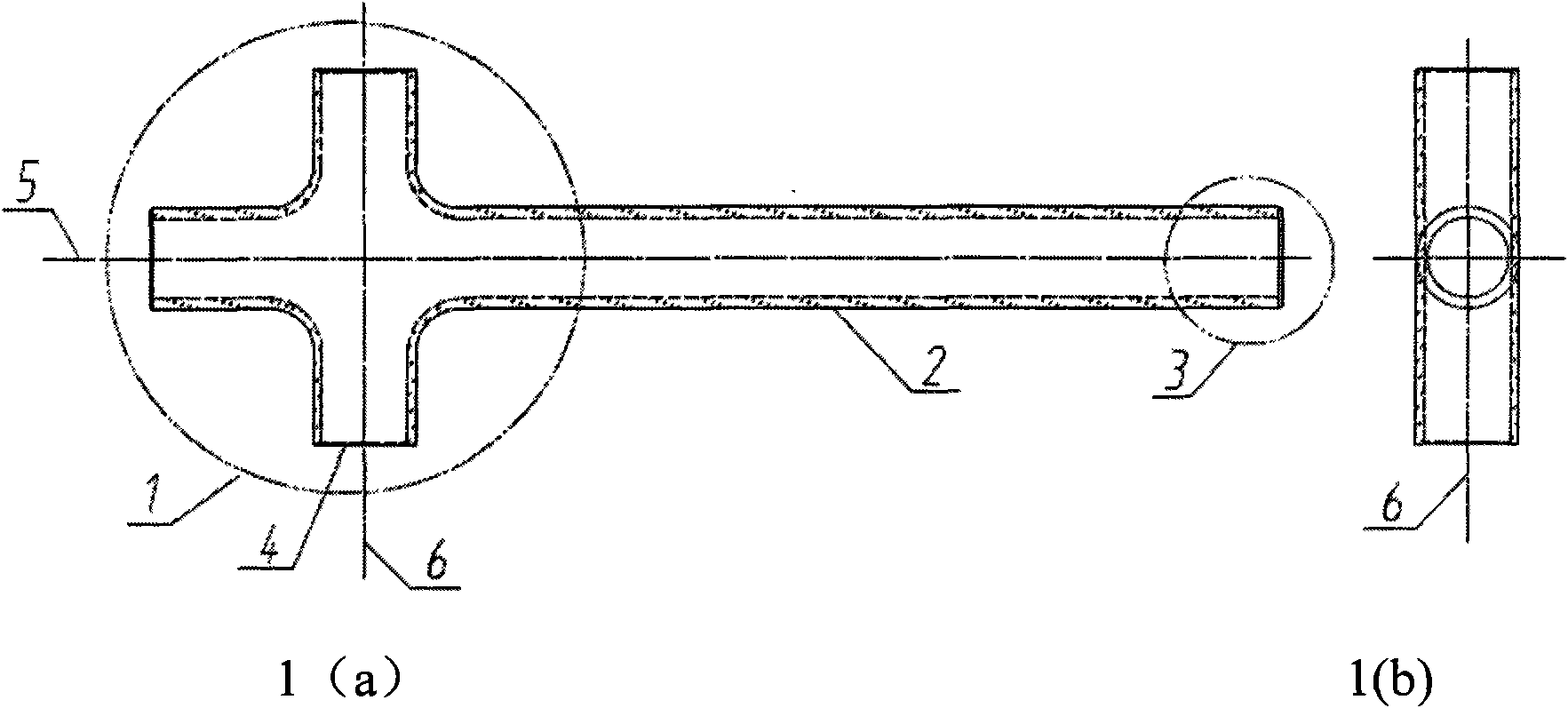
The port of the inlet pipe 4 is also the installation part of the anode needle; the port symmetrical to the inlet pipe 4 is the installation part of the pre-ionization electrode; the horizontal straight pipe part 2 is the glow discharge area, which is also the laser gain oscillation amplification area; the gas outlet part 3 The outside faces the cathode ring; the axis 5 of the horizontal straight pipe 2 intersects the axis 6 of the intake pipe 4, which is an axisymmetric air intake method, which has the disadvantages of insufficient gas turbulence and uneven distribution of the gain medium flow field

Method used


Image

  • Discharge glass tube for axial quick-flow gas laser
  • Discharge glass tube for axial quick-flow gas laser
  • Discharge glass tube for axial quick-flow gas laser

Examples


Embodiment Construction

[0012] Below in conjunction with accompanying drawing and example the present invention is described in further detail.

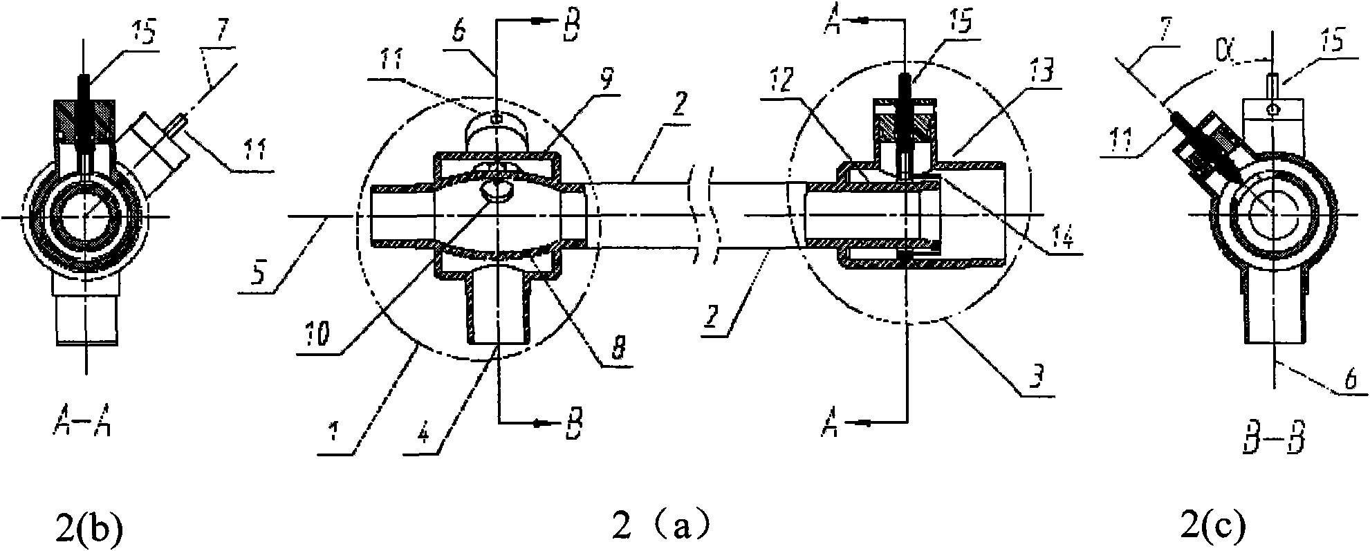
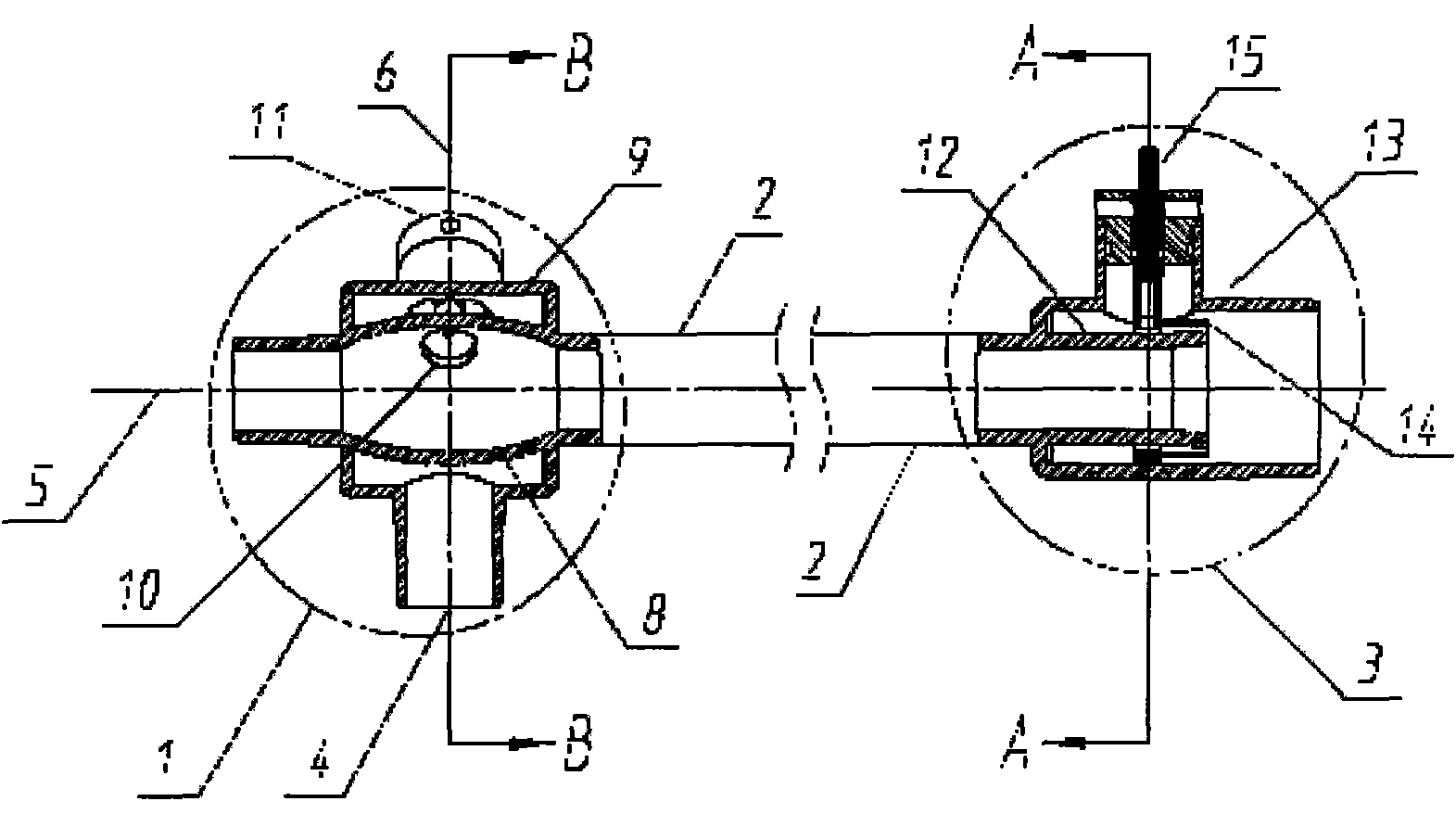
[0013] Such as figure 2 As shown, the structure of the discharge glass tube provided by the present invention is: the vertical air inlet part 1, which is also the installation position of the anode needle; the horizontal straight pipe part 2 is the glow discharge area, which is also the laser gain oscillation amplification area; the horizontal air outlet part 3 , which is also the installation part of the cathode ring;

[0014] The vertical air intake part 1 is a horizontal interlayer "bulge tube" structure with the air intake pipe 4 located at the directly lower end. The longitudinal length of the inner layer bulge tube 8 and the outer layer bulge tube 9 are both greater than the outer diameter of the vertical air intake pipe 4, and the transverse diameter is larger than the horizontal diameter. The outer diameter of the pipe part 2, the horizontal direc...


PUM


Abstract

The invention discloses a discharge glass tube for an axial quick-flow gas laser, which comprises a vertical inlet gas part, a horizontal straight tube part and a horizontal outlet gas part. The inletgas part has a horizontal interlayer swollen tubular structure that a gas inlet pipe is positioned at the right lower end, a vertical inlet gas pipe is communicated with an interlayer between an inner swollen tube and an outer swollen tube and communicated through a pore on the wall of the inner swollen tube, the wall of the outer swollen tube opposite to the pore is provided with an opening forhermetically inserting a metal anode needle stand, and an anode needlepoint is positioned in the center of the pore; the straight tube part and the outlet gas part are in horizontal arc transition connection and are coaxial; and the outlet gas part comprises coaxial inner and outer tubes with open tails. The discharge glass tube is different from an axial symmetry intake mode in the conventional cross discharge tube, and can form full effective turbulence; therefore, the discharge glass tube has the advantages of even, symmetrical and full flow field distribution of a gas gain medium, high injected electric power and the like, structurally ensures stable large-volume glow discharge in the discharge tube, and provides guarantee for acquiring ideal quality of symmetrical, even, stable and reliable output laser beams.

Description

technical field [0001] The invention relates to a laser device, in particular to a discharge glass tube for an axial fast-flow gas laser with replaceable electrodes. Background technique [0002] The discharge glass tube is one of the core units of the axial fast-flow gas laser, and the gas inlet and the gas outlet are respectively provided with an anode and a cathode. Once a high voltage is applied between the cathode and anode electrodes, a gas discharge channel will be formed in the glass tube, and the discharge plasma will quickly pass through the discharge area under the action of an external fan, and part of the electric power injected into the discharge plasma will be converted into The other part of the laser power output is converted into heat energy to increase the temperature of the gas. The high-temperature gas generated by the discharge is cooled by a heat exchanger and then recycled to reduce operating costs and obtain higher photoelectric conversion efficiency...

Claims


Application Information

Patent Timeline
Patent Type & Authority Patents(China)
IPC IPC(8): H01S3/03
Inventor 王又青李波杨扬贺昌玉
Owner HUAZHONG UNIV OF SCI & TECH
Learn More