Method and device for decoding detection

A detection method and detection device technology, applied in the field of decoding detection method and device, can solve the problems of high complexity inversion operation, large storage space, unfavorable DSP and FPGA implementation, etc., to improve computing efficiency, save storage resources, Avoid the effects of the division operation

Active Publication Date: 2013-01-23
HUAWEI TECH CO LTD
View PDF0 Cites 0 Cited by
  • Summary
  • Abstract
  • Description
  • Claims
  • Application Information

AI Technical Summary

Problems solved by technology

[0008] The realization of this method has a large number of division operations that DSP (Digital Signal Processing, digital signal processing) and FPGA (Field-Programmable Gate Array, field programmable gate array) are not good at doing, and contain very high complexity inversion operation, not Conducive to DSP and FPGA implementation;
[0009] Requires a lot of storage space

Method used


Image

  • Method and device for decoding detection
  • Method and device for decoding detection
  • Method and device for decoding detection

Examples


Embodiment 1

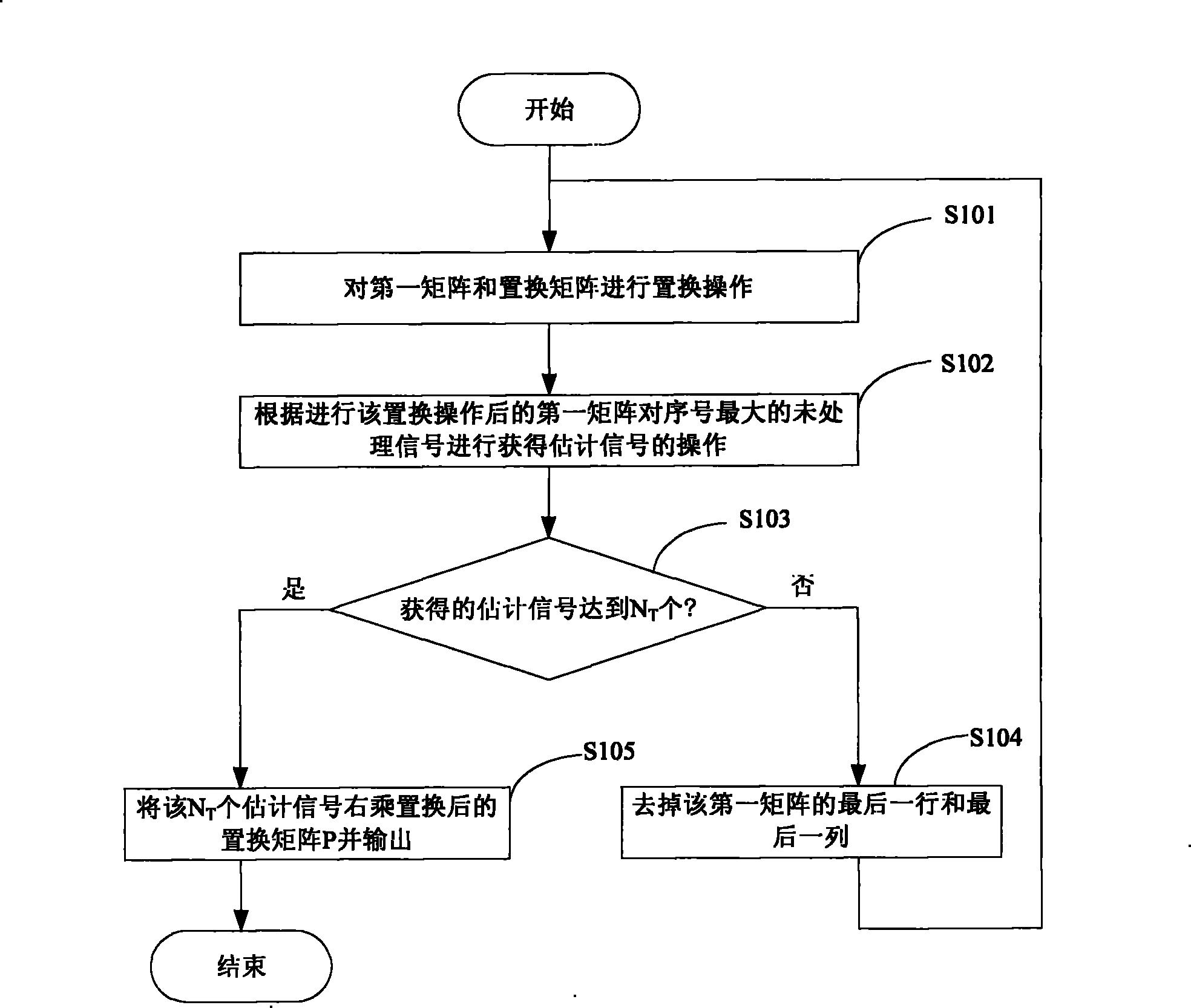
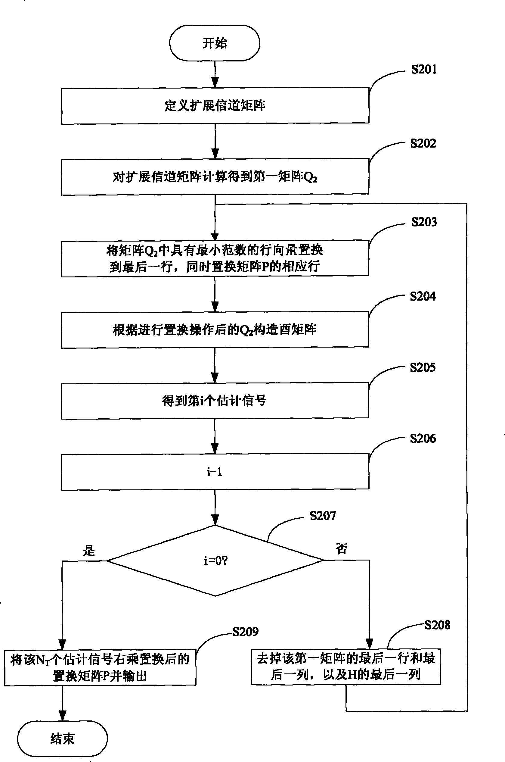
[0035] In this embodiment, the signal detection of the MIMO system is realized by performing two optimization sorts, such as figure 2 As shown, the process of decoding and detection in this embodiment includes the following steps:

[0036] Step S201, set N R ×N T The dimension channel feature matrix H is defined as (N T +N R )×N T Dimensional extended channel matrix H ‾ = H σ · I N T ;

[0037] where σ is the square root of the noise power.

[0038] In this step, the consideration of the influence of noise is added, which can improve the performance of the algorithm.

[0039] Step S202, expanding the channel matrix H Calculate the first matrix, that is, Q un...

Embodiment 2

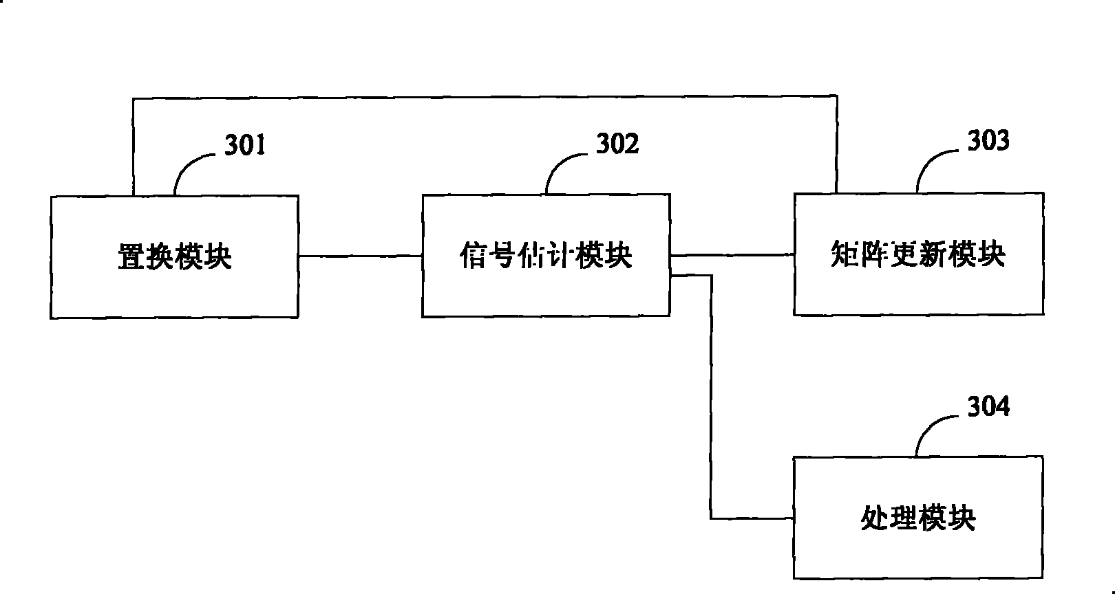
[0072] The decoding detection device in this embodiment, such as image 3 shown, including:

[0073] The replacement module 301 is used to perform a replacement operation on the first matrix and the replacement matrix. The replacement operation is to replace the row vector with the minimum norm in the first matrix to the last row, and replace the corresponding row of the corresponding replacement matrix. The first matrix is The lower left corner N of the unit orthogonal matrix Q obtained by performing orthogonal triangular matrix decomposition on the extended channel matrix under the optimal detection order T ×N T dimension matrix, N T is the number of transmitting antennas for this transmission;

[0074] A signal estimation module 302, configured to obtain an estimated signal on the unprocessed signal with the largest sequence number according to the first matrix after the permutation operation by the permutation module 301;

[0075] Matrix update module 303, used for not...


PUM


Abstract

The invention discloses a method and a device for decoding detection used for improving the efficiency of decoding detection. The method comprises the following steps: carrying out permutation operation for a first matrix and a permutation matrix, namely permuting a row vector with minimum norm in the first matrix to a last row and permuting a corresponding row of the corresponding permutation matrix in the permutation operation, and carrying out orthogonal triangular matrix decomposition for an expanded channel matrix under an optimal detection sequence to acquire an NT*NT-dimensional matrix at the lower left corner of a unit orthogonal matrix by the first matrix, wherein the NT is the transmitting antenna number of the current transmission; according to the first matrix after the permutation operation, carrying out an operation of acquiring an estimation signal for an unprocessed signal with maximum sequence number; removing the last row and the last list of the first matrix, and repeating the permutation operation and the operation of acquiring the estimation signal till acquiring NT estimation signals; and outputting the permutation matrix of the NT estimation signals postmultiplied permutation. The technical proposal of the invention improves the calculation efficiency, and saves storage resources.

Description

technical field [0001] The present invention relates to the field of communication technology, in particular to a decoding detection method and device. Background technique [0002] MIMO (Multiple-Input Multiple-Output) technology refers to using multiple transmitting antennas and receiving antennas at the transmitting end and receiving end respectively, and signals are transmitted and received through multiple antennas at the transmitting end and receiving end. [0003] MIMO systems include two major transmission technologies: multiplexing systems and diversity systems. Among them, the multiplexing system is dedicated to improving the transmission data rate. A typical multiplexing system is the BLAST (Bell Labs Layered Space Time Architecture, Bell Labs Layered Space Time) code system. The BLAST system requires that the antennas be independent, and the subchannels are weak relevant. [0004] The signal model of the V-BLAST (Vertical-BLAST, vertical-Bell Labs layered space...

Claims


Application Information

Patent Timeline
Patent Type & Authority Patents(China)
IPC IPC(8): H04L1/00H04L1/06
Inventor 黄艳宁科
Owner HUAWEI TECH CO LTD
Why Eureka
Try Eureka