Optical imaging splicing device of double CCD image splicing detector

An optical imaging and splicing device technology, applied in the field of CCD detectors, can solve problems such as long time consumption, complicated adjustment process, and complicated adjustment mechanism, and achieve the effect of saving material resources, saving human resources, and simple image position adjustment process

Active Publication Date: 2009-10-21
CHINA NORTH IND NO 205 RES INST
View PDF0 Cites 14 Cited by
  • Summary
  • Abstract
  • Description
  • Claims
  • Application Information

AI Technical Summary

Problems solved by technology

This method of installing a fine-tuning mechanism on one of the CCDs can achieve high stitching accuracy of the target image without post-processing image processing, and can solve the defects of the stitch...

Method used


Image

  • Optical imaging splicing device of double CCD image splicing detector
  • Optical imaging splicing device of double CCD image splicing detector
  • Optical imaging splicing device of double CCD image splicing detector

Examples


Embodiment Construction

[0019] The present invention will be further described in detail below in conjunction with the accompanying drawings and preferred embodiments.

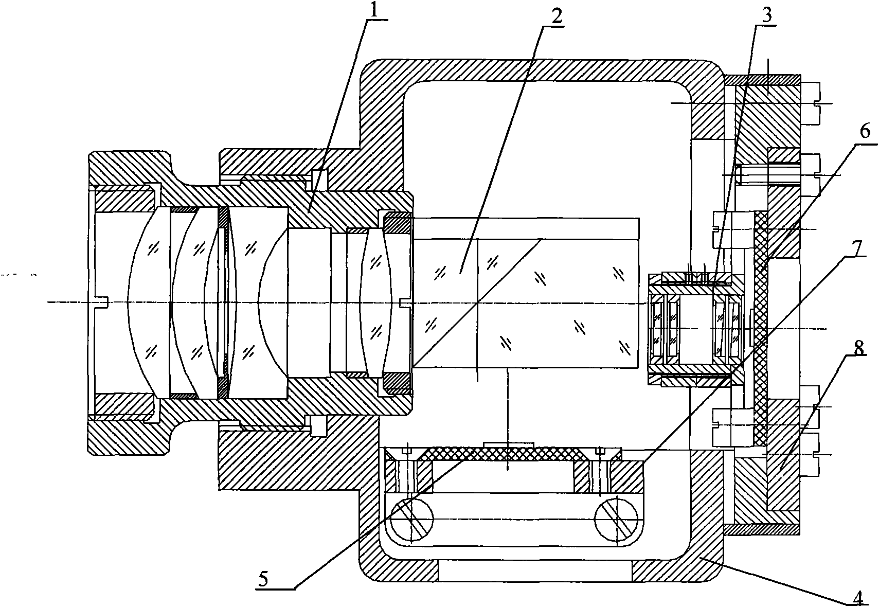
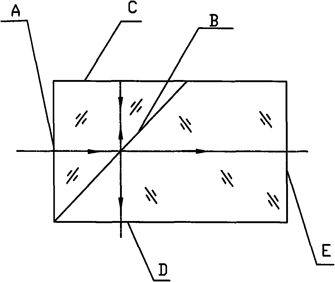
[0020] according to figure 1 As shown, the optical splicing device of the preferred embodiment of the present invention includes an objective lens group 1, a compound prism 2, an optical wedge adjustment mechanism 3, a housing 4, two identical CCD chips 5 and 6, and two connecting plates 7 and 8. The lens barrel of the objective lens group 1 is screwed to the front end of the casing 4 . Composite prism 2 is glued together by a 45° right-angle prism and a 45° wedge-angle prism (see Figure 2a and Figure 2b ), its 45° beam-splitting surface B is coated with a visible light-splitting film layer, the reflectance of the light-splitting film layer is 70%, and the transmittance is 30%; and one of the two right-angled sides of the 45° right-angle prism is used as the light incident surface A, and the other One serves as the light reflect...


PUM


Abstract

The invention discloses an optical imaging splicing device of a double CCD image splicing detector which comprises a casing, an object lens group, a composite prism, two uniform CCDs and an optical wedge adjusting mechanism with two double optical wedge components; the double optical wedge components consist of fixed optical wedges and movable optical wedges; the optical wedge adjusting mechanism is arranged in front of one CCD target surface; and optical wedge angle directions of the two double optical wedge components are mutually perpendicular. In installing and debugging process, two adjusting loop-coils connected with the two movable optical wedges by screw threads are rotated, so as to realize precise alignment of splicing edge pixel of semi target optical imaging focusing on two CCD target surfaces. The device of the invention effectively resolves difficulties of debugging operation in prior optical imaging splicing technique. The device has outstanding advantages of simple structure, light weight, convenient and time-saving debugging and high reliability.

Description

technical field [0001] The invention relates to a CCD detector used in a photoelectric reconnaissance and photoelectric tracking system, in particular to an optical imaging splicing device for a double CCD image splicing detector. Background technique [0002] The photoelectric reconnaissance and tracking system has the advantages of strong target detection ability, high tracking measurement accuracy, strong anti-electromagnetic interference ability, strong concealment, and good confidentiality. It occupies an important position in the weapon system used in modern warfare. [0003] CCD detectors have volume, weight and cost advantages, so they become one of the sensors commonly used in most optoelectronic systems. As a necessary part of the photoelectric reconnaissance detection system, CCD detectors are usually used to track targets and monitor the working status of other tracking systems. It generally consists of a CCD (charge-coupled device) and an optical system. Diffe...

Claims


Application Information

Patent Timeline
IPC IPC(8): H04N5/225H04N17/00G02B7/00
Inventor 杨建忠杨建莉薛小朋白钊
Owner CHINA NORTH IND NO 205 RES INST
Why Eureka
Try Eureka