Combine harvester

A technology for combine harvesters and harvesting devices, which is applied to harvesters, cutters, agricultural machinery and implements, etc. It can solve the problems of loss of adsorption force, easy overheating of the engine, and inability to remove dust, so as to suppress the reduction of the filtration area and improve the efficiency of the filter area. Work efficiency and the effect of ensuring the suction air volume

Inactive Publication Date: 2009-10-28
ISEKI & CO LTD
View PDF1 Cites 3 Cited by
  • Summary
  • Abstract
  • Description
  • Claims
  • Application Information

AI Technical Summary

Problems solved by technology

However, in the prior art described in the above-mentioned patent document 1, the central part of the rectangular dust-proof net is used as the axis to rotate and drive the suction wind shielding plate to gradually partially shield the suction wind passing through the dust-proof net, so that the dust is lost to the dust-proof net. The structure that falls due to the adsorption force
That is, the relatively rectangular dust filter makes the suction wind shielding plate rotate in a circular trajectory, so the dust attached to the corner of the dust filter cannot be removed, and the intake air volume through the dust filter decreases, and the cooling efficiency of the radiator and the engine decreases. , the disadvantage that the engine is easy to overheat

Method used


Image

  • Combine harvester
  • Combine harvester
  • Combine harvester

Examples


Embodiment Construction

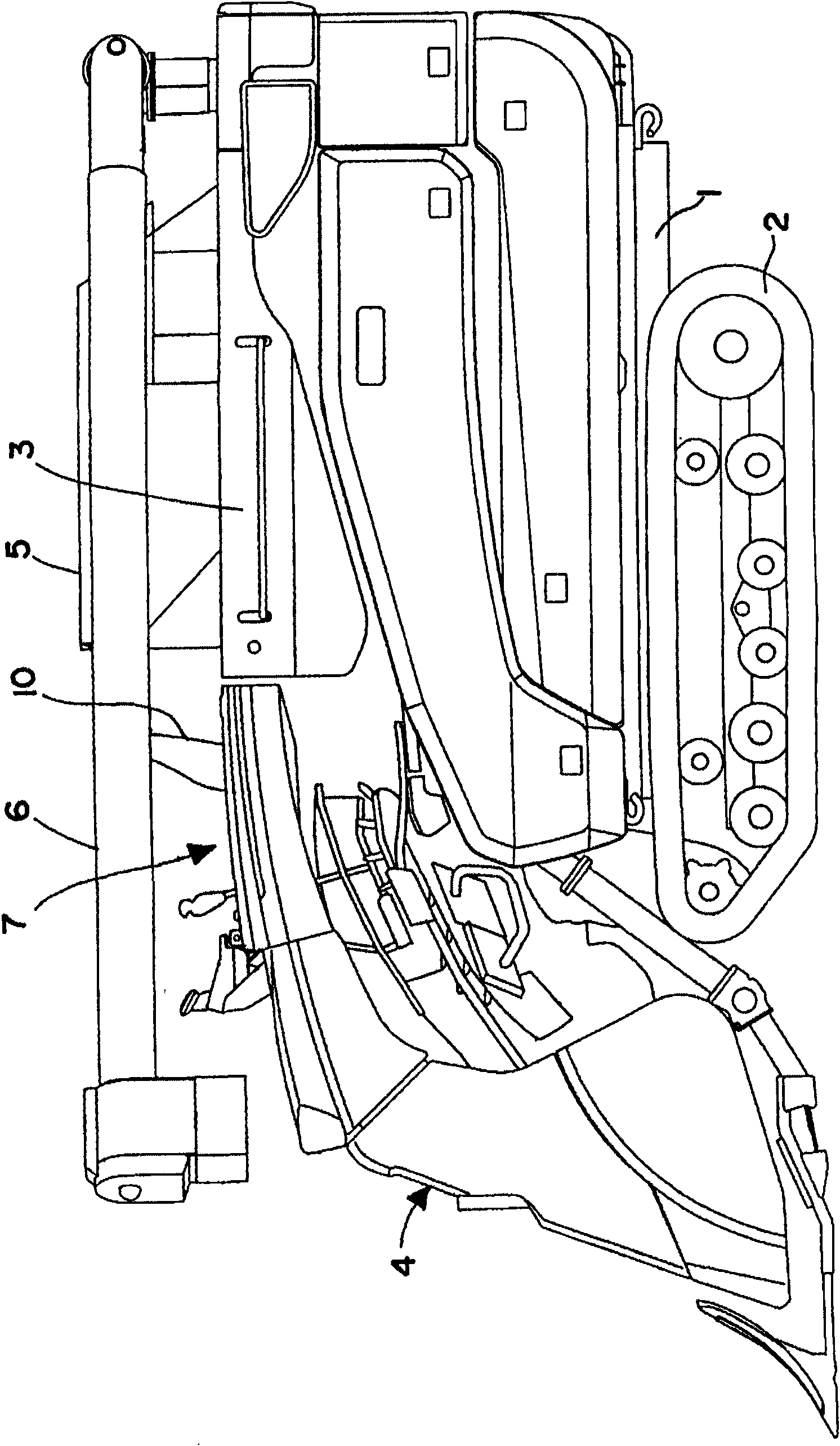
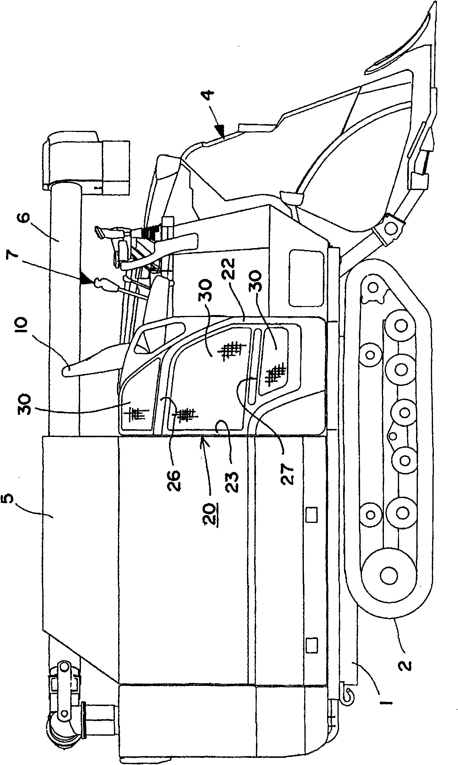
[0038] Such as figure 1 , figure 2 As shown, the body structure of the combine harvester of the present invention is such that a crawler-type traveling device 2 is provided on the lower side of the body frame 1, and a threshing device 3 and a grain threshing device 3 equipped with an auger 6 are mounted side by side on the upper side of the body frame 1. The storage device 5 is provided with the manipulation part 7 on the front side of this grain storage device 5, and the reaping device 4 is provided in the front side of the body frame 1 so that it can move up and down freely.

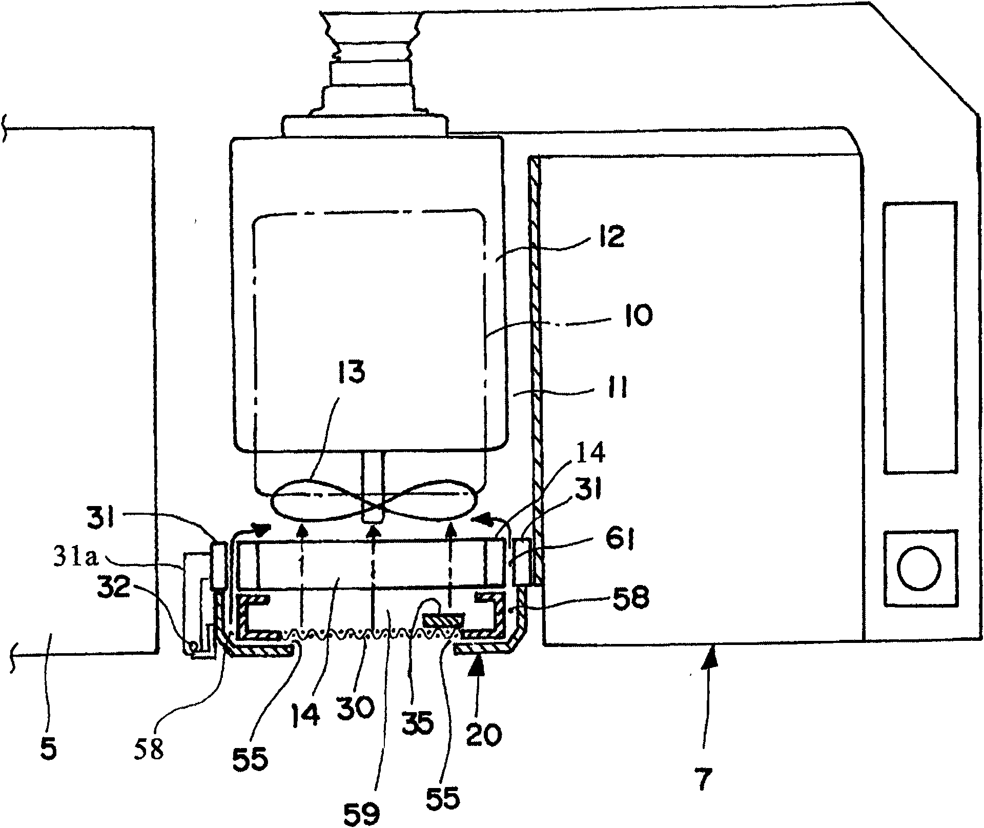
[0039] Furthermore, an engine 12 is mounted on the upper side of the body frame 1 below the driver's seat 10 of the control unit 7 , and the engine 12 is surrounded by a partition wall to form an engine room 11 . An engine cooling fan 13 driven by the engine 12 is provided on the body frame 1 on the outer side of the body than the engine 12 . A radiator 14 for cooling the engine 12 is provided on th...


PUM


Abstract

The invention relates to a combine harvester, ensures the intake air quantity passing through the dustproof net for cooling, prevents the engine from overheating, and improves the work efficiency of the combine harvester. an intake air shield plate (35) for shielding part of the intake air passing through the dustproof net (30) is disposed near the inner side surface of the dustproof net (30); and a driving device is disposed for driving the intake air shield plate (35) to perform a reciprocating motion linearly along the inner side surface of the dustproof net (30); in addition, a dust attraction mouth (55) for attracting the dust on the outer surface of the dustproof net (30) is disposed on the end of the reciprocating motion path of the intake air shield plate (35); additionally, an accessory attraction duct (58) from the dust attraction mouth (55) to the cooling fan (13) is separated from the main attraction duct (59) from the dustproof net (30), through the radiator (14) to the cooling fan (13).

Description

technical field [0001] The present invention relates to combine harvesters. Background technique [0002] Existing combine has following structure as disclosed in patent document 1 (Japanese Patent Laying-Open No. 2002-59748). A radiator is provided outside the cooling fan equipped on the engine. In the dust net, a suction wind shielding plate having a predetermined width is provided inside the dustproof net, and a driving device for rotationally driving the suction wind shielding plate is provided. [0003] Dust such as rice straw scraps is adsorbed on the outside of the dustproof net by the suction wind of the cooling fan, but the suction wind passing through the dustproof net is gradually and partially shielded by the rotation drive of the suction wind shielding plate, so that the dust is lost to the dustproof net. The adsorption force of the dust net falls down, and the overheating of the engine is prevented by the dust net being blocked. [0004] Generally, the dust f...

Claims


Application Information

Patent Timeline
Patent Type & Authority Applications(China)
IPC IPC(8): A01D41/02A01D41/12B60K11/08
Inventor 藤田靖上路嘉隆
Owner ISEKI & CO LTD
Why Eureka
Try Eureka