Composite sleeve double-helix heat exchanger

A composite casing, shell-and-tube heat exchanger technology, applied in the direction of heat exchanger type, indirect heat exchanger, lighting and heating equipment, etc., can solve the problem of poor fluid circulation, low flow rate, limited improvement of shell-side circulation, etc. problems, to achieve the effect of increasing heat transfer coefficient, increasing heat transfer intensity and rate, and decreasing convective heat transfer thermal resistance

Inactive Publication Date: 2009-10-28
赵文阁
View PDF0 Cites 32 Cited by
  • Summary
  • Abstract
  • Description
  • Claims
  • Application Information

AI Technical Summary

Problems solved by technology

At present, it is recognized that the most advanced pseudo-helical baffle heat exchanger has limited improvement on the shell side circulation. Even if the full spiral manufacturing is technically realized or the shell side is d

Method used


Image

  • Composite sleeve double-helix heat exchanger
  • Composite sleeve double-helix heat exchanger
  • Composite sleeve double-helix heat exchanger

Examples


Embodiment 1

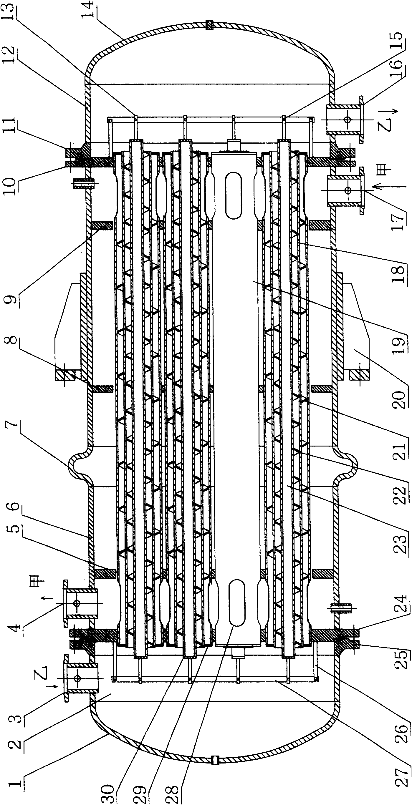
[0028] Composite casing double-helix heat exchanger, its composition includes: a cylinder 6 with a fluid inlet 17, an outlet 4 and an expansion joint 7, the left inner tube plate 5 is fixed near the left end of the cylinder 6, and the The left end of the cylindrical body 6 is fixed with a left outer tube plate 24, the near right end of the cylindrical body 6 is fixed with a right inner tube plate 9, the right end of the cylindrical body 6 is fixed with a right outer tube plate 10, the cylindrical body 6 An intermediate support tube plate 8 is fixed in the middle, a support 20 is fixed in the middle of the cylinder 6, the left end of each outer tube 19 of the heat exchange tube bundle is fixed on the left outer tube plate 24, and the right outer tube The right end of each outer tube 19 of the heat exchange tube bundle is fixed on the plate 10, the left end of the outer tube 19 is fixed on the left end of the outer tube 29, and the right end of the outer tube 19 is fixed on the r...

Embodiment 2

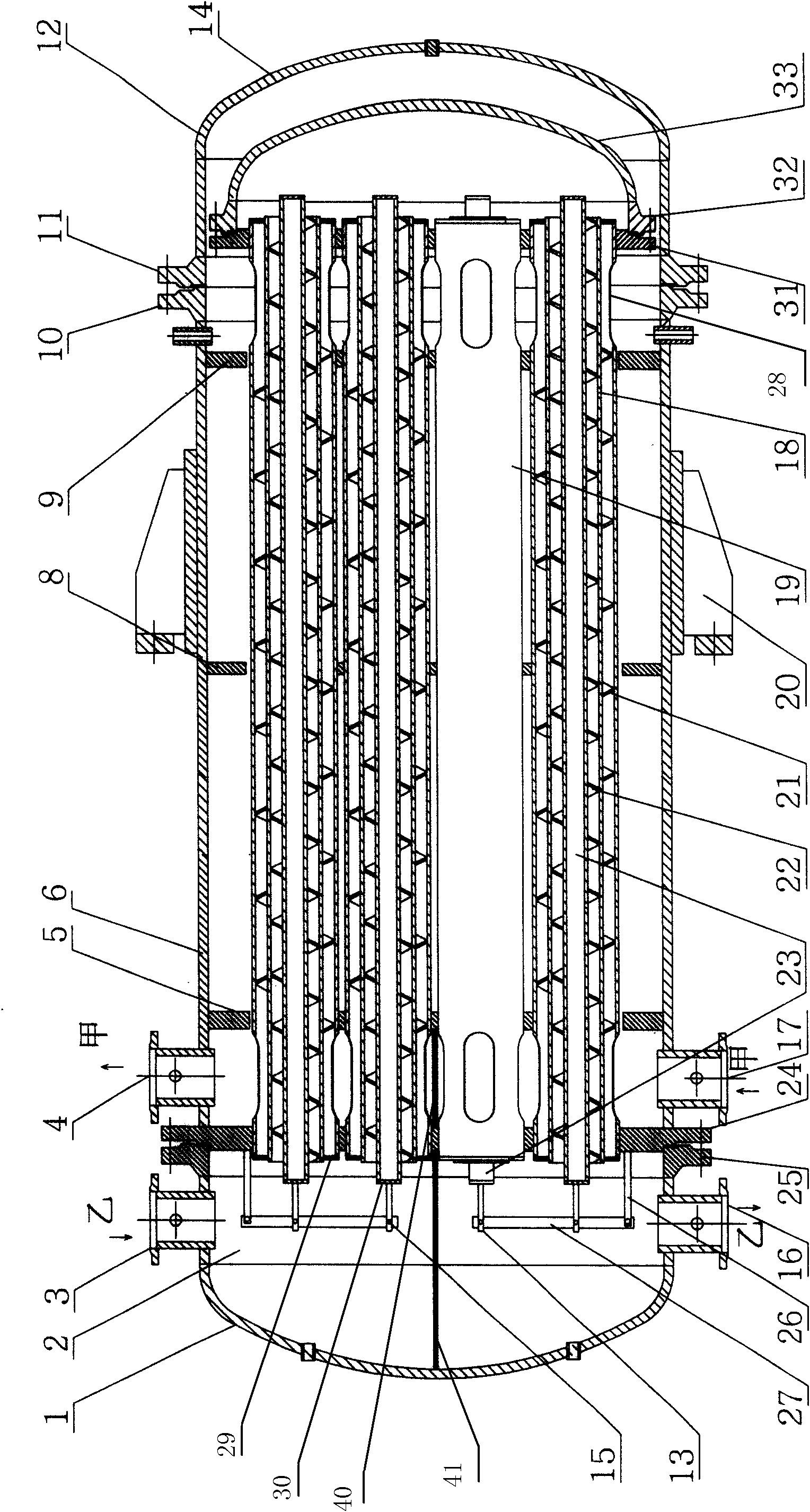
[0031] Composite casing double-helix heat exchanger, its composition includes: a cylinder 6 with a fluid inlet 17, an outlet 4 and an expansion joint 7, the left inner tube plate 5 is fixed near the left end of the cylinder 6, and the A left outer tube plate 24 is fixed at the left end of the cylinder body 6, a right inner tube plate 9 is fixed near the right end of the cylinder body 6, a cylinder right flange 10 is fixed at the right end of the cylinder body 6, and the cylinder body The middle part of 6 is fixed with an intermediate support tube plate 8, the middle part of the cylinder body 6 is fixed with a support 20, the left outer tube plate 24 is fixed with a partition 40, and the left outer tube plate 24 is fixed with a replacement The left end of each outer tube 19 of the heat pipe bundle, the right end of each outer tube 19 of the heat exchange tube bundle is fixed with a floating head tube plate 31, and the floating head tube plate 31 is connected to the floating head...

Embodiment 3

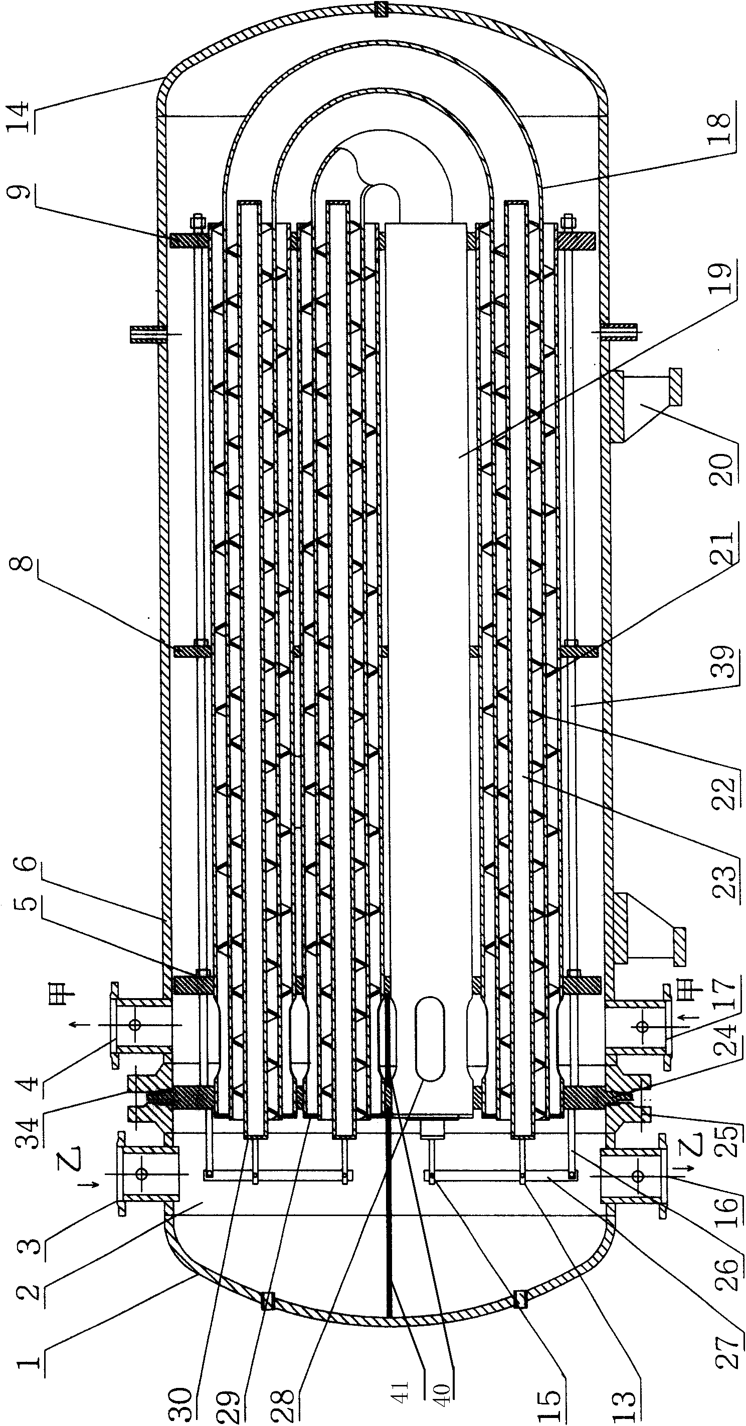
[0034] Composite casing double-helix heat exchanger, its composition includes: a cylinder 6 with a fluid inlet 17, an outlet 4 and an expansion joint 7, the left end of the cylinder 6 is fixed with a cylinder left flange 34, the cylinder The right end of the body 6 is fixed with a cylinder right head 14, the middle part of the cylinder 6 is fixed with a support 20, the cylinder left flange 34 is sealed and connected with the left outer tube plate 24, and the left outer tube A partition 40 is fixed on the plate 24, the left end of each outer tube 19 of the heat exchange tube bundle is fixed on the left outer tube plate 24, and the left inner tube plate 5 is fixed near the left end of each outer tube 19, A right inner tube plate 9 is fixed near the right end of each of the outer tubes 19, an intermediate support tube plate 8 is fixed in the middle of each of the outer tubes 19, and a left end blocking plate of the outer tube is fixed on the left end of the outer tube 19. 29. The...


PUM


Abstract

The invention relates to a composite sleeve double-helix heat exchanger. At present, a plate type heat exchanger has high coefficient of heat transfer but can bear lower working pressure; a pipe shelltype heat exchanger is of a pressure-resisting structure but has very low coefficient of heat transfer; and a pipe type heat exchanger is formed by a single heat exchanging pipe or a heat exchange pipe bundle and has low heat transfer rate due to thick viscous flow layer of liquid inside the pipe and poor circulation state due to very low flow rate of liquid outside the pipe. In a double-helix three-sleeve heat exchanging pipe bundle of the composite sleeve double-helix heat exchanger, a middle pipe and a hollow inner pipe form an inner flow passage; inner helical blades are arranged in an annular gap of the middle pipe and the inner pipe; an outer pipe and the middle pipe form an outer flow passage; outer helical blades with opposite handedness with the inner helical blades are arranged in an annular gap of the middle pipe and the outer pipe; and two-phase liquid fast forms an annular lamella in the pipe to flow forwards in a helical scouring way. The structure not only has strong structure, but also can greatly improve the heat-transfer characteristic of the heat exchanger.

Description

Technical field: [0001] The invention relates to a chemical unit operation equipment, more specifically, it is a new shell-and-tube heat exchanger with outer, middle and inner three-layer composite sleeves and countercurrent reverse double helix structure. Background technique: [0002] At present, 90% of heat exchangers are shell and tube heat exchangers, followed by plate heat exchangers, etc. This is because most of the industrial occasions are high temperature and high pressure. A plate heat exchanger with a heat transfer coefficient as high as 2-3 times that of a shell-and-tube heat exchanger can withstand a lower working pressure of only 2-3.5 MPa. In a shell-and-tube heat exchanger, the heat exchange tube bundle is a circle The tube and the shell are cylinders, both of which are pressure-resistant structures, and the equipment can reach a working pressure of 30-35MPa. People have tried to improve the structure of the plate heat exchanger to withstand high pressure, b...

Claims


Application Information

Patent Timeline
IPC IPC(8): F28D7/10F28D7/02
Inventor 赵文阁
Owner 赵文阁
Why Eureka
Try Eureka