Deicing device for high-voltage power transmission cable

A technology of high-voltage transmission lines and lighting devices, which is applied in the installation of cables, overhead installations, electrical components, etc., and can solve problems that affect production and life, low efficiency, and economic losses

Inactive Publication Date: 2009-10-28
SHANDONG UNIV
View PDF0 Cites 20 Cited by
  • Summary
  • Abstract
  • Description
  • Claims
  • Application Information

AI Technical Summary

Problems solved by technology

[0002] Freezing rain and snow accumulation in winter often lead to ice accumulation on transmission cables. If the ice accumulation is not removed for a long time, it will seriously threaten the safe operation of the power grid. The accidents caused by cable ice accumulation have caused huge economic losses to the country.
Damage to hardware, brittle cables, and even tilting or collapse of towers caused by severe ice accumulation often lead to large-scale power outages and affect people's normal production and life
[0003] At present, there are two main ways of deicing: one is artificial deicing, that is, sending electric workers to beat the ice accumulation with wooden sticks, which is inefficient, has great limitations, and is very dangerous; the other is short-circuit ice melting, that is, Let the circuit be short-circuited instantly to generate heat and deicing, but this method will inevitably lead to power interruption, and the energy consumption is huge, but the effect is not ideal
Judging from the prior art, there is no efficient and practical deicing machine for high-voltage transmission lines

Method used


Image

  • Deicing device for high-voltage power transmission cable
  • Deicing device for high-voltage power transmission cable
  • Deicing device for high-voltage power transmission cable

Examples


Embodiment

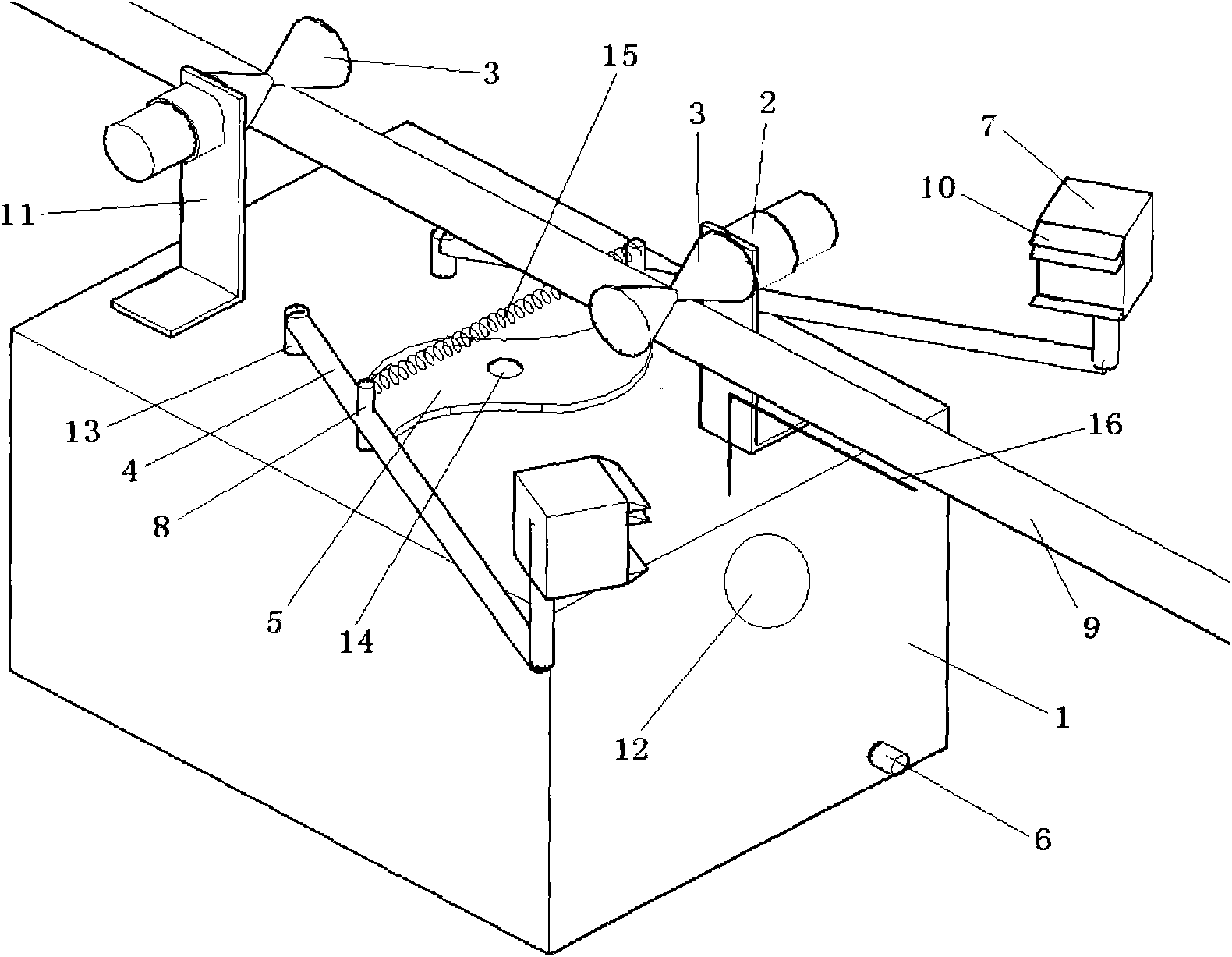
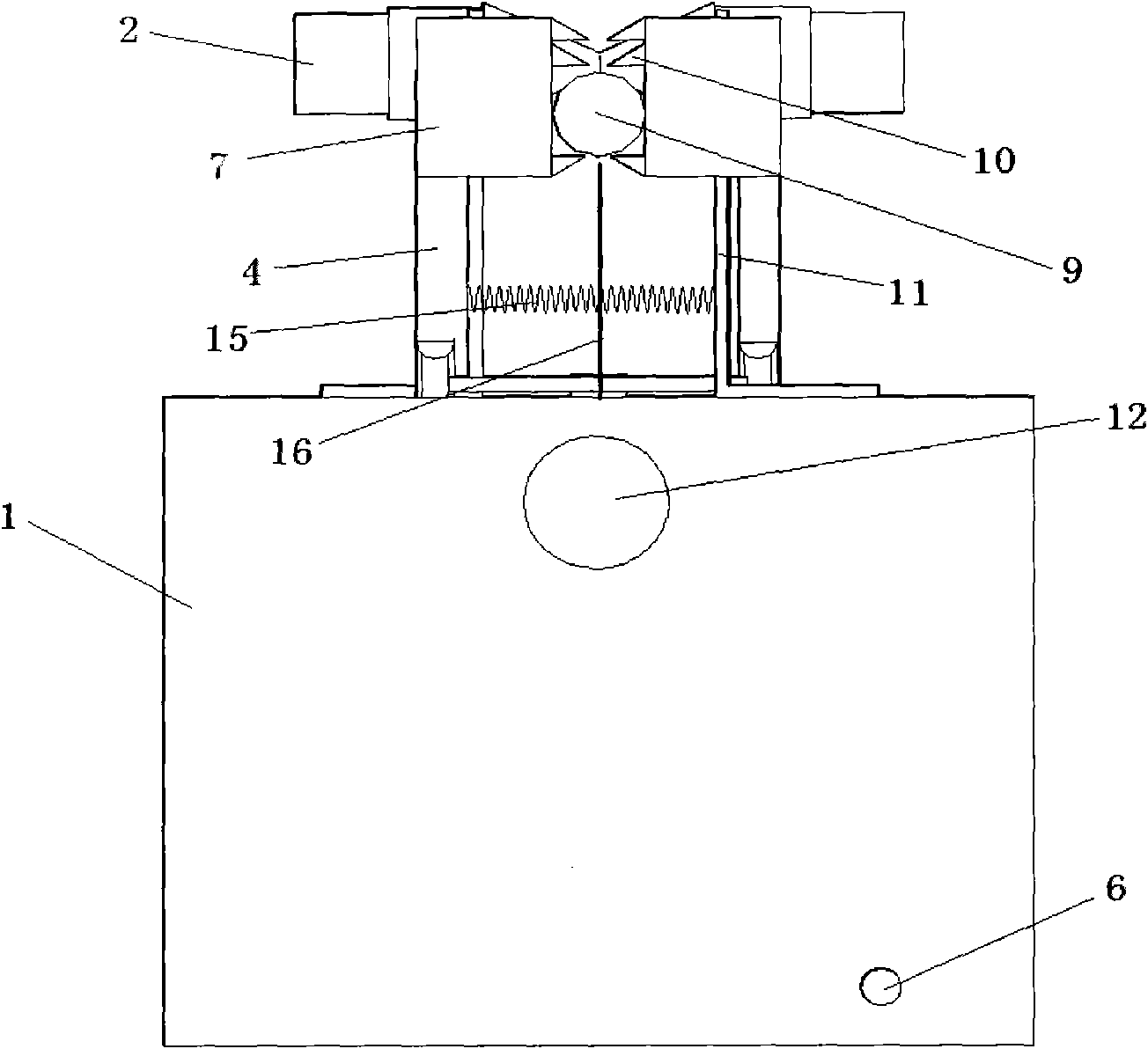
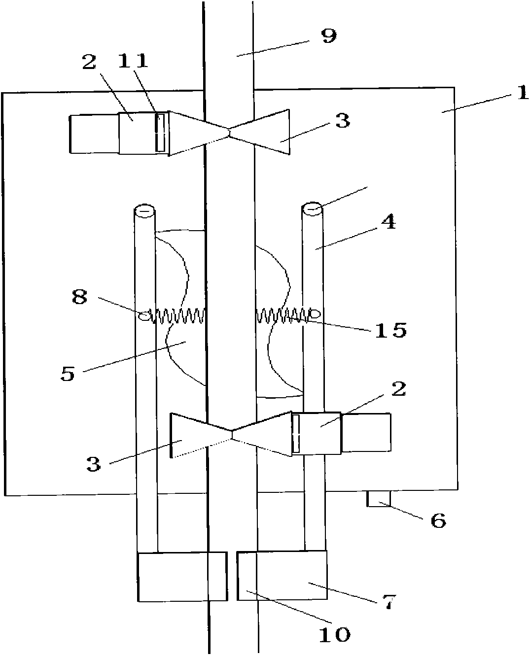
[0027] Examples of the present invention Figure 1-6 As shown, it consists of a host 1, a beating device, and a walking device. It is characterized in that the host 1 includes a microprocessor 17, a power supply 18, a wireless receiving module 19, an ice accumulation detector, a limit switch 21, a motor drive module 20, and an alarm. The detector module 22 and the lighting device 12; the wireless receiving module 19, the limit switch 21, the motor drive module 20, the alarm module 22 and the lighting device 12 are respectively connected with the microprocessor through the I / O port; The probe 16 is connected to the limit switch 21. The L-shaped probe 16 is installed in the middle of the front end of the shell of the host 1. When the L-shaped probe 16 touches the ice accumulation, it is pushed back to generate displacement and push the limit The action of the switch 21 generates a level conversion signal; the power supply 18 is connected to the microprocessor 17, the wireless re...


PUM


Abstract

The invention provides a deicing device for a high-voltage power transmission cable, and belongs to a high-voltage power transmission auxiliary device. The device consists of a host, a striking device and a traveling device, wherein a wireless receiving module, a limit switch, a motor driving module, an alarm module and an illuminator, which are arranged on the host, are connected with a micro processor respectively; an L-shaped probe is arranged at the front end of a shell of the host; a power supply is connected with and supplies power for all circuit modules in the host; the striking device is provided with two striking rods, one end of each striking rod is provided with a striking hammer and the other end of the striking rod is fixed on the shell of the host through a bearing, and the striking rods can rotate around the bearings; a friction rod is arranged between the striking rods, and the two striking rods are fixedly provided with springs; the shell of the host is fixedly provided with a motor, and a rotary shaft of the motor is fixedly provided with a cam; two support racks of the traveling device are fixed on the shell of the host respectively, and the two support racks are fixedly provided with two driving motors of which rotary shafts are fixedly provided with traveling wheels; control switches of the motor of the striking device and the two driving motors are connected with the motor driving module respectively. The device is practical and can be conveniently and safely used.

Description

1. Technical field [0001] The invention relates to a high-voltage power transmission cable deicing device, which belongs to a high-voltage power transmission auxiliary device. 2. Background technology [0002] Freezing rain and snow accumulation in winter often lead to ice accumulation on transmission cables. If the ice accumulation is not removed for a long time, it will seriously threaten the safe operation of the power grid. The accidents caused by cable ice accumulation have caused huge economic losses to the country. Damage to hardware, brittle cables, and even tilting or collapse of towers caused by severe ice accumulation often lead to large-scale power outages and affect people's normal production and life. [0003] At present, there are two main ways of deicing: one is artificial deicing, that is, sending electric workers to beat the ice accumulation with wooden sticks, which is inefficient, has great limitations, and is very dangerous; the other is short-circuit ic...

Claims


Application Information

Patent Timeline
Patent Type & Authority Applications(China)
IPC IPC(8): H02G7/16
Inventor 王汉斌宣堃田韶存林涛张中晗陈言俊
Owner SHANDONG UNIV
Why Eureka
Try Eureka