Refrigerant system with economizer, intercooler and multi-stage compressor

A refrigerant system and refrigerant technology, applied in the direction of compressors, irreversible cycle compressors, refrigerators, etc., can solve the problems of low feasibility of intercoolers, improve the performance of refrigerant systems, improve reliability, and high Effect of refrigerant cooling potential

Inactive Publication Date: 2009-10-28
CARRIER CORP
View PDF0 Cites 26 Cited by
  • Summary
  • Abstract
  • Description
  • Claims
  • Application Information

AI Technical Summary

Problems solved by technology

However, the additional cost and complexity of the wiring and components associated with the intercooler and economizer makes intercooler less feasible

Method used


Image

  • Refrigerant system with economizer, intercooler and multi-stage compressor
  • Refrigerant system with economizer, intercooler and multi-stage compressor

Examples


Embodiment Construction

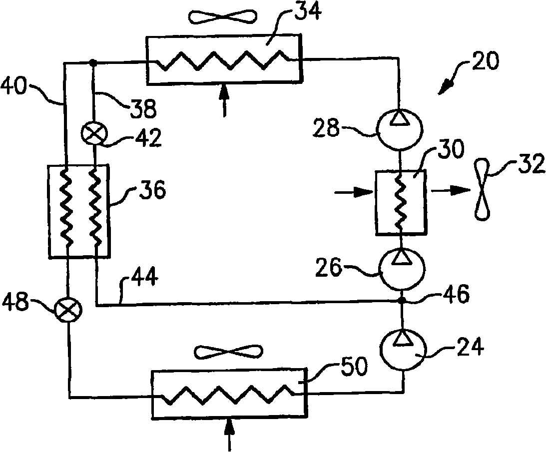
[0017] figure 1 A refrigerant system 20 is illustrated. Three compression stages 24, 26 and 28 are arranged in series in refrigerant system 20 to asymptotically compress the refrigerant from suction pressure to discharge pressure. While multi-stage compressor systems are represented by separate compressor units arranged in series, such as figure 1 shown, but a separate compression member could be used instead of some or all of the compressor unit. Specifically, for example in the case of a three-stage reciprocating compressor, three separate compression members may represent different banks of cylinders connected in series. The refrigerant compressed by the first stage from the suction pressure to the first intermediate pressure is transported from the discharge port of the first stage to the suction port of the second stage. Refrigerant vapor is compressed by the second stage to a second intermediate pressure and conveyed from the discharge of the second stage to the sucti...


PUM


Abstract

A refrigerant system is provided with a multi-stage compression system. An intercooler is positioned between at least two compression stages to cool a refrigerant, by heat transfer interaction with a secondary fluid, after it has been compressed in the lower compression stages to some intermediate pressure. The intercooler enhances refrigerant system performance, improves compressor reliability, and extends operational envelope. Further, at least one economizer circuit is incorporated into the refrigerant system that returns the economized refrigerant flow at the location between at least two compression stages.

Description

technical field [0001] The present application relates to a refrigerant system with a multi-stage compressor that combines the advantages of an intercooler heat exchanger and an economizer cycle. In particular, the present application relates to refrigerant systems that operate in a transcritical cycle at least part of the time. Background technique [0002] Refrigerant systems are known, which are used to condition the secondary fluid. For example, air conditioning systems cool and dehumidify the air that is sent into a climate-controlled environment. [0003] A basic refrigerant system consists of a compressor which compresses the refrigerant and sends it downstream through the discharge line to a first heat exchanger which is what is called a condensate for subcritical applications coolers or gas coolers for transcritical applications. In the first heat exchanger, heat is removed from the refrigerant by a secondary medium, eg ambient air. The refrigerant from the firs...

Claims


Application Information

Patent Timeline
Patent Type & Authority Applications(China)
IPC IPC(8): F25B1/00
CPCF25B2400/13F25B1/10F25B2309/06F25B2400/072
Inventor A·利夫森M·F·塔拉斯
Owner CARRIER CORP
Why Eureka
Try Eureka