Seed cotton foreign fiber separator

A technology of foreign fiber and separator, which is applied in the direction of separating plant fiber from seeds, fiber treatment, fiber cleaning, etc., to achieve good cleaning effect

Active Publication Date: 2009-11-04
SHIHEZI UNIVERSITY
View PDF1 Cites 33 Cited by
  • Summary
  • Abstract
  • Description
  • Claims
  • Application Information

AI Technical Summary

Problems solved by technology

[0006] The purpose of the present invention is to provide a seed cotton foreign fiber separator that has good cleaning effect, especially can effectively remo...

Method used


Image

  • Seed cotton foreign fiber separator
  • Seed cotton foreign fiber separator
  • Seed cotton foreign fiber separator

Examples


Embodiment 1

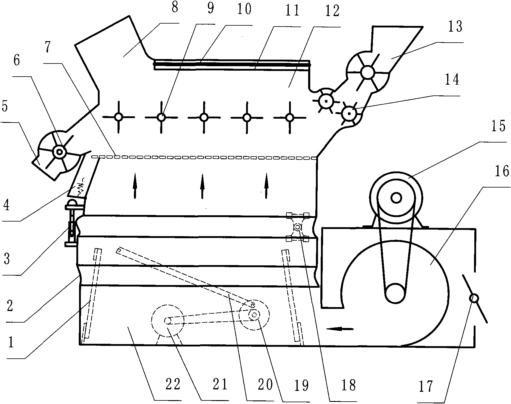
[0021] Refer to attached figure 1 , figure 2 , is a structural schematic diagram of Embodiment 1 of the present invention, including a separation chamber 12 composed of an electrode plate group and a box, a fan 16 and an air chamber 22, a fan 16, and the fan 16 is installed in a closed box, and the air inlet is provided with an air volume regulating plate 17 , to control the air intake, the fan is driven by a motor 15, the separation chamber 12 is provided with a feed inlet 13, a discharge outlet 5 and a miscellaneous outlet 8, and the miscellaneous outlet 8 is located on the oblique upper side of the separation chamber 12, and the The passages of the feed inlet 13 and the discharge outlet 5 are equipped with air locks to prevent the air volume in the separation chamber from being lost and cause insufficient air volume for exhausting impurities. Effective removal, the above-mentioned discharge port is connected with the cathode plate to be provided with a stone discharge por...

Embodiment 2

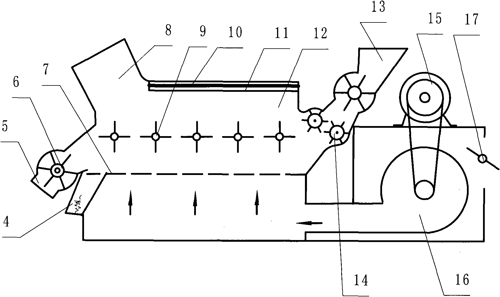
[0023] refer to image 3 , is a structural schematic diagram of Embodiment 2 of the present invention. This embodiment includes a separation chamber 12, a fan 16, and an air chamber 22 composed of an electrode plate group and a box body. The fan 16 is installed in a closed box, and the air inlet is provided with an air volume. Adjusting plate 17, fan is driven by motor 15, and separation chamber 12 is provided with feed inlet 13, discharge outlet 5 and miscellaneous outlet 8, and miscellaneous discharge opening 8 is located at the oblique top of separation chamber 12 side, and described The passages of the feed port 13 and the discharge port 5 are provided with an air lock, and the joint between the discharge port and the cathode plate is provided with a stone discharge port 4, and the stone discharge port is provided with a closeable stone discharge gate. Also be provided with conveying pair roller 14 in the channel of mouth 13, described electrode plate group is made up of a...

Embodiment 3

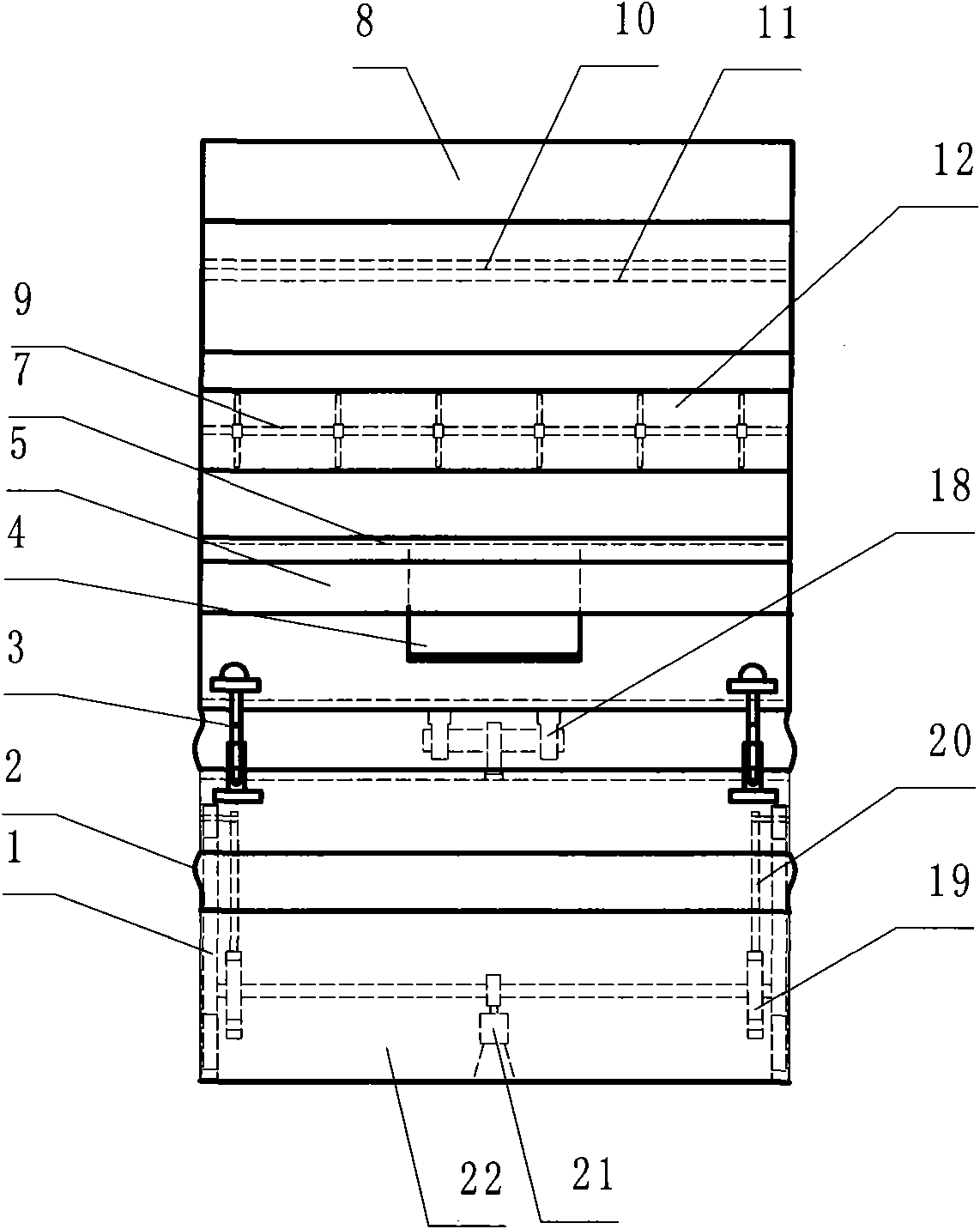
[0025] refer to Figure 4 , is a structural schematic diagram of Embodiment 3 of the present invention. Compared with Embodiment 1, the difference of this embodiment is that the vibrating device under the separation chamber is mainly composed of a crank 19, a connecting rod 20 and a motor 21, and the cathode plate 7 and The stirring device is arranged on a suspended underframe 23 inside the separation chamber 12 , and the connecting rod 20 is connected with the suspension frame 23 .


PUM


Abstract

The invention discloses a seed cotton foreign fiber separator which comprises a separating chamber consisting of an electrode plate set and a case body, a feeding port, a discharge port, an impurity discharge port, a fan and a wind chamber. The electrode plate set consists of an anode plate and a cathode plate. The electrode plate of the electrode plate set, which is positioned between the separating chamber and the wind chamber, is a wind-evening network-shaped structure. The seed cotton foreign fiber separator is characterized in that a stirring device is arranged between the anode plate and the cathode plate in the separating chamber, and at least one stirring and shifting roller constitutes a stirring and shifting roller set. Compared with the prior art, the seed cotton foreign fiber separator can effectively clear foreign fibers such as mulching films, and the like during cotton picking, and meanwhile can clear other impurities, and the clearing effect is good.

Description

Technical field: [0001] The invention relates to a seed cotton foreign fiber separator. Background technique: [0002] At present, foreign fibers in cotton refer to non-cotton fibers that are mixed into cotton during the production, processing and circulation of seed cotton and have a serious impact on the quality of cotton and its products, such as chemical fibers, hair, silk, plastic films or ropes, dyed fibers, etc. Thread, or cloth, etc., colored fibers, chemical fibers, and hair are commonly known as "three silks". Foreign fibers mixed into seed cotton are easily broken into scattered single fibers, which are difficult to remove in textile processing. When spinning, scattered single fibers are easy to break the cotton yarn and reduce production efficiency. When weaving, it affects the quality of the cloth surface. When dyeing, the different coloring affects the appearance, causing great harm to the quality of cotton yarn and cloth surface. When printing and dyeing cot...

Claims


Application Information

Patent Timeline
IPC IPC(8): D01G9/00D01B1/02D01B9/00
Inventor 张若宇坎杂江英兰王丽红李景彬李成松张海军黄勇安红磊孟繁碧胡万超彭涛
Owner SHIHEZI UNIVERSITY
Why Eureka
Try Eureka