Zoom lens

A technology of zoom lens and mirror group, applied in the field of zoom lens

Active Publication Date: 2009-11-04
ASIA OPTICAL CO INC
View PDF2 Cites 2 Cited by
  • Summary
  • Abstract
  • Description
  • Claims
  • Application Information

AI Technical Summary

Problems solved by technology

[0005] Although there are published literatures disclosing the method of thinning the zoom lens, it cannot be said to be a good method from the perspective of optical performance.

Method used


Image

  • Zoom lens
  • Zoom lens
  • Zoom lens

Examples


Embodiment Construction

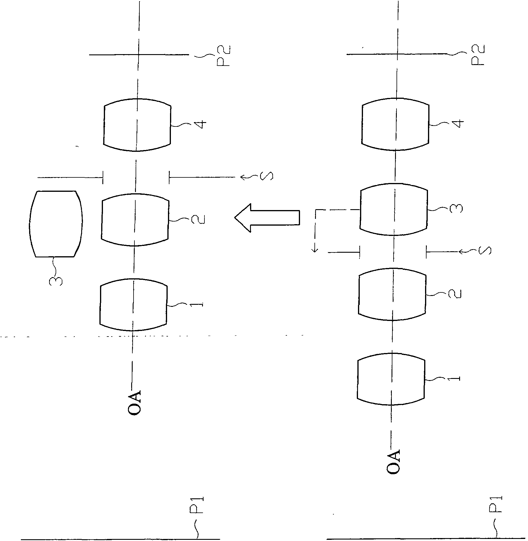
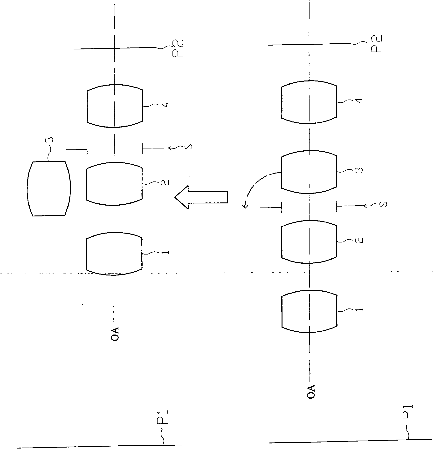
[0023] Figure 1A and Figure 1B It is a schematic diagram showing the zoom lens of the present invention in zoom operation and storage state. Please refer to Figure 1A and Figure 1B As shown, the zoom lens has four lens groups, which are the first lens group 1 , the second lens group 2 , the aperture stop S, the third lens group 3 and the fourth lens group 4 . When the zoom lens is zooming, these lens groups are located on a common optical axis OA, and a first plane P1 and a second plane P2 are conjugate planes through the zoom lens. For example, when the zoom lens is used in a camera device, the first plane P1 is the object end and the second plane P2 is the image end; when the zoom lens is used in a projection device, the first plane P1 is the zoom end and The second plane P2 is the narrowing end. When the zoom lens performs a zoom operation, at least one lens group can move along a common optical axis OA.

[0024] When the zoom lens of the present invention is stored...


PUM


Abstract

The invention provides a zoom lens comprising a plurality of lens groups. During zooming operation, the lens groups are arranged at a common optical axis and enable a first plane and a second plane to be conjugate planes mutually through the zoom lens; when the zoom lens is retracted, at least one lens group turns to the outside of the common optical axis by a shaft vertical to the common optical axis and moves towards the first plane, and at least one left lens group moves from the first plane towards the second plane in the direction parallel to the common optical axis, thereby enabling the total length of the zoom lens being retracted to be shortened so as to be an ultrathin zoom lens.

Description

technical field [0001] The invention relates to a zoom lens, in particular to a zoom lens suitable for electronic devices and thinned after storage. Background technique [0002] With the continuous development of science and technology, the integration of portable electronic devices, such as notebook computers, mobile phones, personal digital assistants (PDAs) or palm-sized projectors, etc., with optoelectronic technology has become one of the trends of today's technological development. For example, a camera-capable mobile phone is the integration of a mobile phone and a lens, which can be used as a typical representative of this integration technology trend. The lens of a camera phone not only needs to have good image quality, but also needs to have a smaller volume and lower cost. [0003] In order to reduce the lens size and manufacturing cost, aspherical lenses are often used in current lens designs. Aspherical lenses can avoid the spherical aberration produced by sp...

Claims


Application Information

Patent Timeline
Patent Type & Authority Applications(China)
IPC IPC(8): G02B15/16G02B7/04
Inventor 阪本宇正
Owner ASIA OPTICAL CO INC
Why Eureka
Try Eureka