Method for cleaing molten steel for continuous casting tundish by air curtain retaining wall method

A continuous casting tundish and gas curtain retaining wall technology, which is applied in the field of steelmaking and continuous casting, can solve the problems of secondary pollution and insignificant removal effect of small inclusions, save gas source, reduce secondary pollution, and achieve good effect. Effect

Inactive Publication Date: 2011-11-16
WUHAN UNIV OF SCI & TECH
View PDF0 Cites 0 Cited by
  • Summary
  • Abstract
  • Description
  • Claims
  • Application Information

AI Technical Summary

Problems solved by technology

A large number of studies have shown that by setting retaining walls and other flow control technologies, it is only effective for the removal of inclusions larger than 50 μm, and the removal effect for small inclusions (less than 50 μm) is not obvious. secondary pollution

Method used


Image

  • Method for cleaing molten steel for continuous casting tundish by air curtain retaining wall method
  • Method for cleaing molten steel for continuous casting tundish by air curtain retaining wall method
  • Method for cleaing molten steel for continuous casting tundish by air curtain retaining wall method

Examples


Embodiment 1

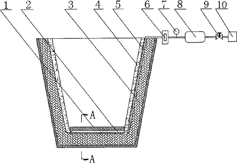
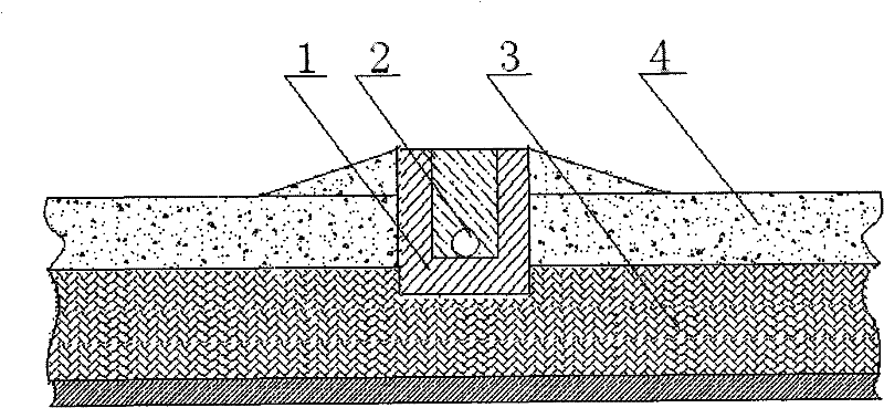
[0015] A method for cleaning molten steel in continuous casting tundish air curtain retaining wall, such as figure 1 Shown: Slots are made on the bottom of the tundish and the permanent layer 3 near the side wall of the air source, and the breathable brick 1 is embedded in the groove of the permanent layer 3 at the bottom of the tundish. The upper air-permeable surface of the breathable brick 1 is as follows figure 2 The working layer 4 that is slightly higher than the bottom of the tundish is shown; the groove of the permanent layer 3 near the side wall of the gas source is embedded in the groove of the permanent layer 3, and one end of the argon connecting pipe 5 is connected to the breathable brick embedded in the groove at the bottom of the tundish The air-permeable chamber 2 of 1 communicates, and the other end of the argon gas connection 5 protrudes upward along the permanent layer 3 groove of the side wall and passes through the flow meter 6, pressure gauge 7, buffer ga...

Embodiment 2

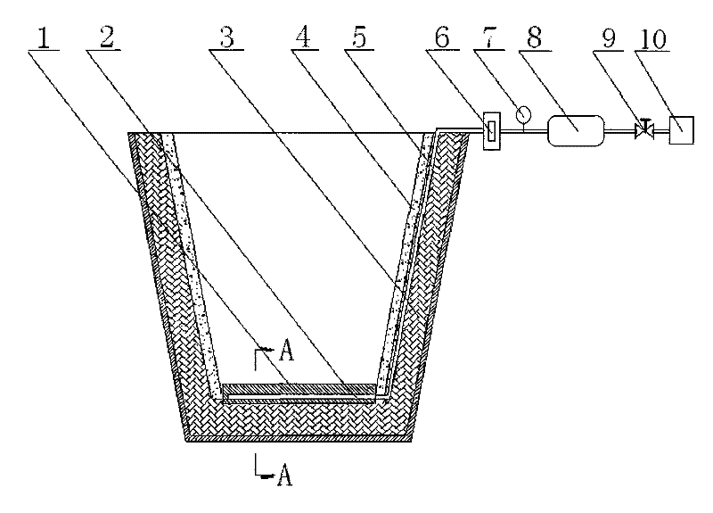
[0020] A method for cleaning molten steel in continuous casting tundish air curtain retaining wall, such as figure 1 Shown: Slots are made on the bottom of the tundish and the permanent layer 3 close to the side wall of the gas source, the ventilating brick 1 is embedded in the groove at the bottom of the tundish, and the upper ventilating surface of the ventilating brick 1 is flush with the working layer 4 built on the bottom of the tundish . The air permeability of the air brick is 25-40μm 2 , the width of the upper air-permeable surface is 50-60mm; the groove depth of the permanent layer 3 at the bottom of the tundish is 10-15mm, the groove width is 90-100mm, and the groove length is the same as the width of the working layer 4 at the bottom of the tundish; The groove depth of the permanent layer 3 on the side wall of the source is 10-15 mm, the groove width is 10-15 mm, and the groove length is the distance from the bottom of the tundish to the edge of the tundish.

[00...


PUM


Abstract

The invention relates to a continuous casting method of pouring box air curtain retaining wall clean molten steel. The adopted technical proposal is as follows: slotting a permanent layer (3) on the bottom of the pouring box and a permanent layer (3) close to the lateral wall of an air source, embedding an air brick (1) in the slot of the permanent layer (3) at the bottom of the pouring box with the upper ventilation surface of the air brick (1) paralle and level to or a little higher than a working layer (4) built at the bottom of the pouring box; embedding an argon connecting pipe (5) in theslot of the permanent layer (3) close to the lateral wall of the air source with one end of the argon connecting pipe (5) communicated with a ventilation chamber (2) of the air brick (1) embedded inthe slot on the bottom of the pouring box and the other end thereof extending upward along the slot of the permanent layer (3) close to the lateral wall and being connected with an argon source (10) through a flow meter (6), a pressure gauge (7), a buffering air tank (8) and a valve (9) outside the pouring box; and adopting smearing material to infill the construction gaps for embedding the air brick (1) and the argon connecting pipe (5). The method is conducive to eliminating inclusion due to collided growth, can improve the flow characteristic of molten steel and eliminate minute non-metallic inclusion, and effectively improves the purity of molten steel.

Description

technical field [0001] The invention belongs to the technical field of steelmaking and continuous casting. In particular, the invention relates to a method for cleaning molten steel in a continuous casting tundish air curtain retaining wall. Background technique [0002] With the development of continuous casting technology, the demand for ultra-pure steel continues to increase, and the requirements for the cleanliness of molten steel are also getting higher and higher. Improving the cleanliness of molten steel is the basis for improving the quality of steel. The refining technology outside the furnace and the use of high-quality refractory materials can reduce the impurity factors and inclusions in molten steel to a very low level. [0003] However, in actual production, the clean molten steel after refining goes through the tundish and crystallizer into the steel slab pulled out from the continuous casting machine. did not achieve the desired goal. Therefore, people use...

Claims


Application Information

Patent Timeline
Patent Type & Authority Patents(China)
IPC IPC(8): B22D11/11
Inventor 顾华志黄奥汪厚植张美杰
Owner WUHAN UNIV OF SCI & TECH
Why Eureka
Try Eureka