
Fuel cell with humidification zone of single cell

A technology for fuel cells and single cells, applied in fuel cells, fuel cell additives, fuel cell grouping, etc., can solve problems such as the performance difference of single cells, improve power density and energy density, reduce power consumption, improve The effect of stability

Inactive Publication Date: 2009-11-11
TSINGHUA UNIV
View PDF6 Cites 25 Cited by
  • Summary
  • Abstract
  • Description
  • Claims
  • Application Information

AI Technical Summary

Problems solved by technology

Due to the uneven gas distribution, it is easy to cause the difference in the performance of the single battery, which will be amplified after the stack works for a long time

Method used


Image

  • Fuel cell with humidification zone of single cell
  • Fuel cell with humidification zone of single cell
  • Fuel cell with humidification zone of single cell

Examples


Embodiment 1

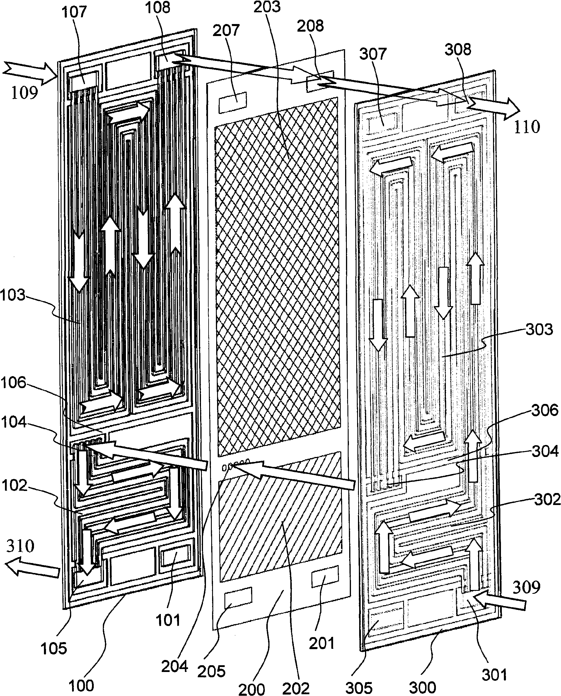
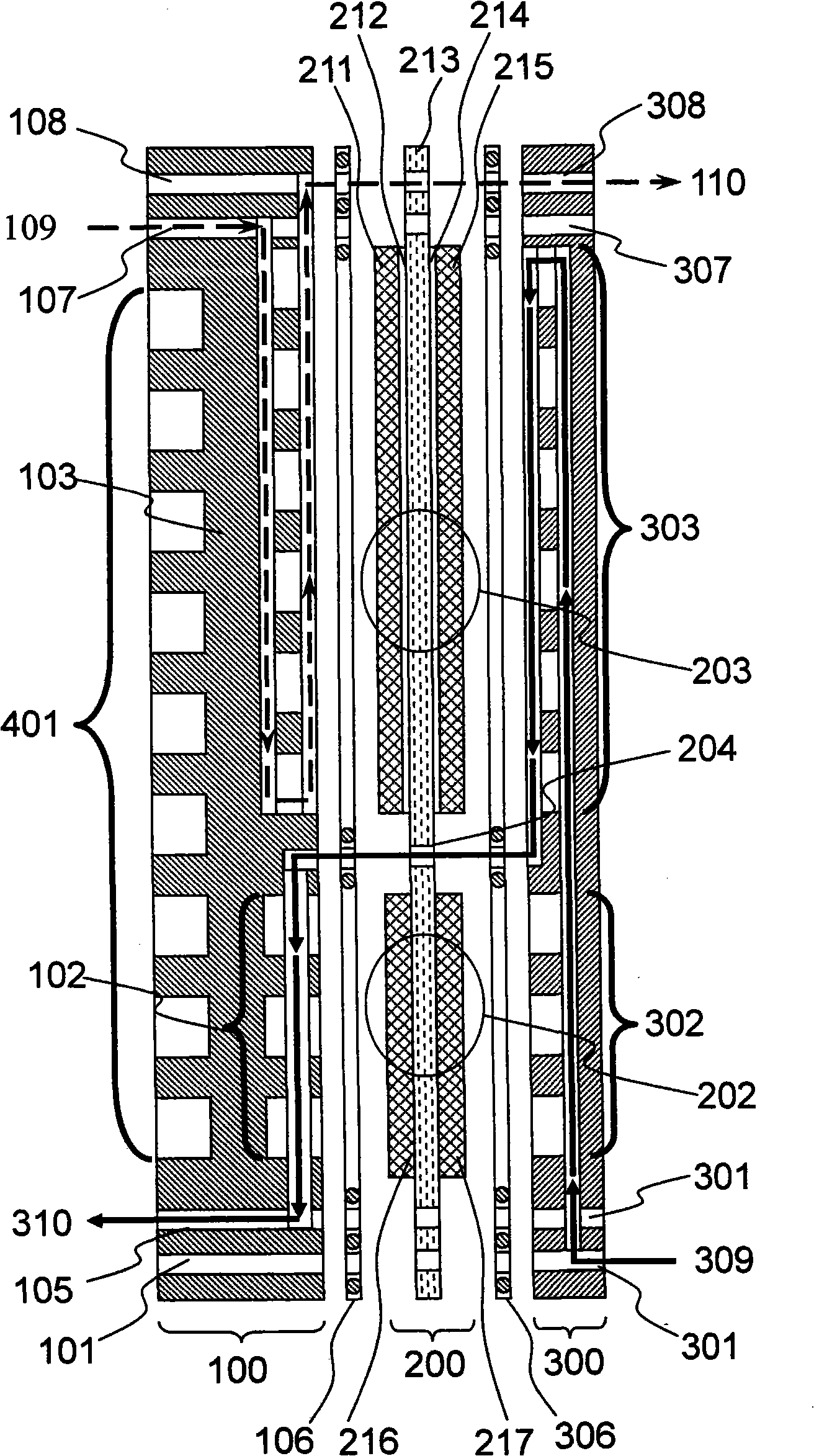
[0048] figure 1 and figure 2 One embodiment of the invention is shown in . The fuel cell with single cell humidification area of ​​the present invention is formed by stacking two or more fuel cell cells, figure 1 It shows a schematic diagram of the three-dimensional decomposition structure of a single fuel cell of the invention, figure 2 It is a schematic side view of a single fuel cell. From figure 1 As can be seen in the figure, the fuel cell unit contains an anode flow field plate 100, a membrane electrode 200 and a cathode flow field plate 300 in sequence, wherein the fuel cell unit membrane electrode 200 includes a humidification zone 202 and a reaction zone 203, and the anode flow field The plate 100 includes an anode humidification flow field 102 and an anode gas reaction flow field 103 , and the cathode flow field plate 300 includes a cathode humidification flow field 302 and a cathode gas reaction flow field 303 . The positions of the anode gas reaction flow fi...

Embodiment 2

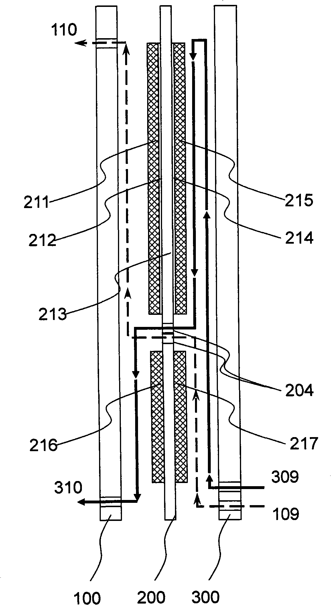
[0055] image 3Shown is a simplified schematic diagram of another embodiment utilizing air tail gas to simultaneously humidify the anode gas and cathode gas feeds. In this embodiment, the flow mode of the cathode gas is the same as that in the first embodiment, the difference is that when the anode gas enters the single fuel cell, it first flows through the humidification flow field 302 on the cathode flow field plate 300 . At this time, the humidification flow field on the cathode flow field plate is divided into two parts, one part is the anode gas humidification flow field, and the other part is the cathode gas humidification flow field. The chambers are separated from each other by a seal 306 to prevent the anode gas and cathode gas from mixing with each other. The corresponding membrane electrode humidification area is also divided into two parts: the anode gas humidification area and the cathode gas humidification area. After the anode gas enters the anode gas humidifi...


PUM


Abstract

The invention discloses a fuel cell with the humidification zone of a single cell. The fuel cell is formed by the superposition of a plurality of monomers; each monomer comprises a cathode flow field plate, an anode flow field plate, a sealing element and a membrane electrode, wherein the membrane electrode consists of a reaction zone and a humidification zone, and corresponding reaction zones and humidification zones are also included in the anode flow field plate and the cathode flow field plate. After entering the monomers of the fuel cell, the cathode reaction air firstly passes through the humidification zone of the cathode flow field plate and then enters the reaction zone to participate in an electrochemical reaction, and later enters the humidification zone on the anode flow field plate through an air channel arranged on the membrane electrode, and water in tail gas can humidify the entering gas by penetrating a proton exchange membrane in the humidification zone of the membrane electrode. The fuel cell directly utilizes the tail gas of air to humidify the entering gas; and as the humidification zone and the reaction zone are on the same membrane electrode, and the structure is simple, the water management of the fuel cell can be greatly simplified and the power density of the system can be improved. The fuel cell can be applied to various fields such as uninterruptible power supply systems, electric vehicle engine systems, and the like.

Description

technical field [0001] The invention belongs to the field of fuel cells, in particular to the proton exchange membrane fuel cell technology using no external humidification. Background technique [0002] A fuel cell is a continuous power generation device that converts chemical energy in externally supplied fuel and oxidant into electrical energy. Because of its high power density and energy density, clean and efficient, and wide power range, fuel cells have broad application prospects in various fields such as micro power sources, mobile power sources, vehicle engines, and stationary power stations, so they have received extensive attention from countries all over the world. The United States, Japan, Canada, and European countries are actively developing fuel cell technology. At present, almost all major automakers in the world are developing fuel cell electric vehicles. [0003] The current fuel cell technology is mainly divided into several types according to different e...

Claims


Application Information

Patent Timeline
IPC IPC(8): H01M8/24H01M8/02H01M4/86H01M8/04H01M8/0289H01M8/04828H01M8/2465
CPCY02E60/50
Inventor 刘志祥王诚毛宗强
Owner TSINGHUA UNIV
Learn More