Optical film and its production method, and glare-proof polarizer using same and display apparatus

A technology of optical film and manufacturing method, which is applied in the field of optical film, can solve problems such as deterioration of anti-glare properties, and achieve the effects of suppressing reflection, good clarity of transmitted images, and good visibility

Inactive Publication Date: 2009-11-11
SONY CORP
View PDF3 Cites 9 Cited by
  • Summary
  • Abstract
  • Description
  • Claims
  • Application Information

AI Technical Summary

Problems solved by technology

However, there arises such a problem that if the smoothing of the concave-convex portion is achieved by prolonging the period of the concave-convex portion on the surface of the antiglare layer 112 intentionally as described above, the binder between the protrusions of the fine particles 113 A flat part is formed in the part, so that the anti-glare property deteriorates

Method used


Image

  • Optical film and its production method, and glare-proof polarizer using same and display apparatus
  • Optical film and its production method, and glare-proof polarizer using same and display apparatus
  • Optical film and its production method, and glare-proof polarizer using same and display apparatus

Examples


no. 1 approach

[0103] (1-1) Structure of liquid crystal display device

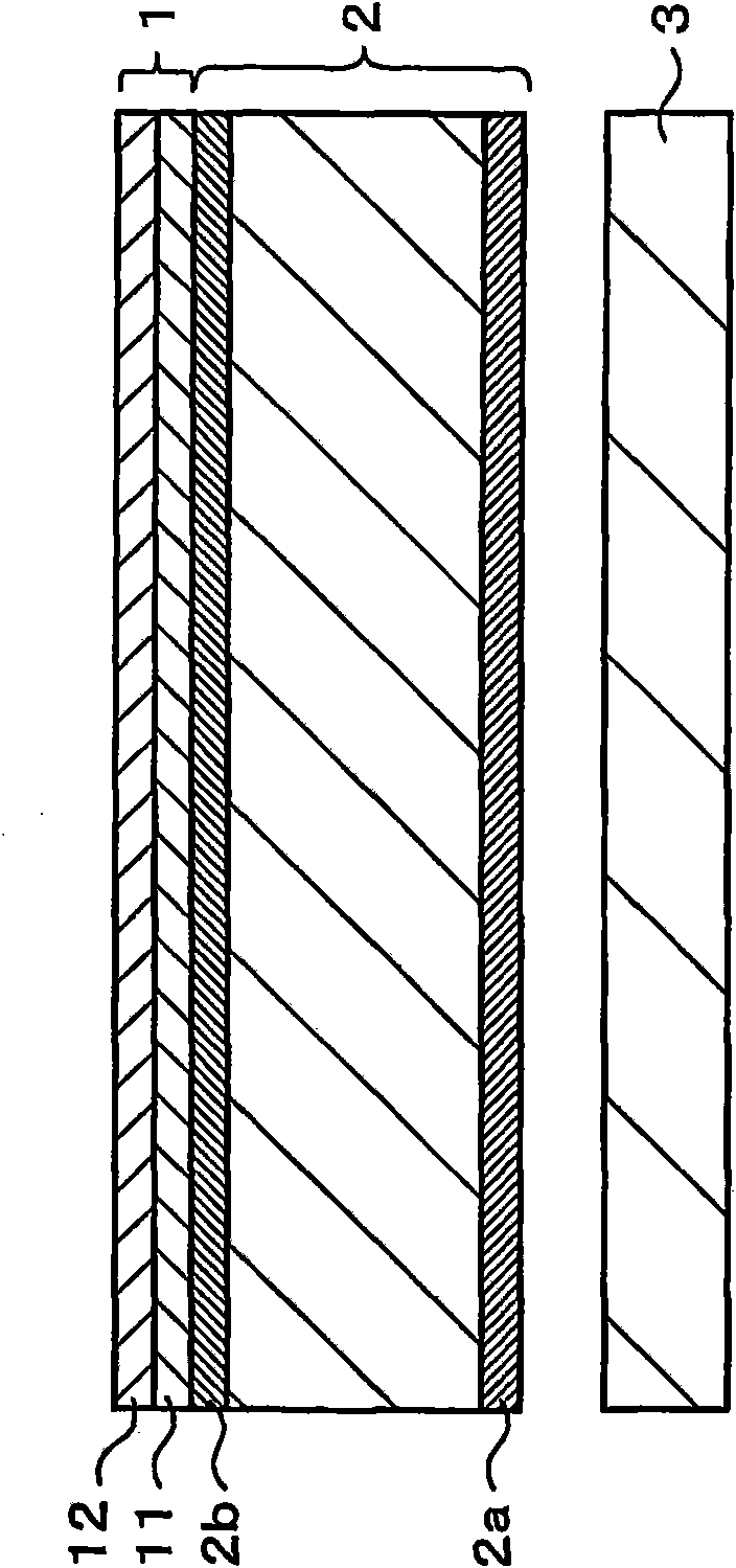
[0104] image 3 One example of the configuration of the liquid crystal display device according to the first embodiment of the present invention is shown. Such as image 3 As shown, the liquid crystal display device includes: a backlight 3 for emitting light; and a liquid crystal panel 2 for temporally and spatially adjusting the light emitted from the backlight 3 and displaying an image. Polarizers 2a and 2b are provided on both surfaces of the liquid crystal panel 2, respectively. The anti-glare film 1 is provided on the polarizing plate 2 b provided on the display surface side of the liquid crystal panel 2 .

[0105] As the backlight 3 , for example, a direct type backlight, an edge type (edge ​​type) backlight, or a planar light source type backlight can be used. The backlight 3 includes, for example, a light source, a reflection plate, an optical film, and the like. As the light source, for example, CCFL (Cold...

no. 2 approach

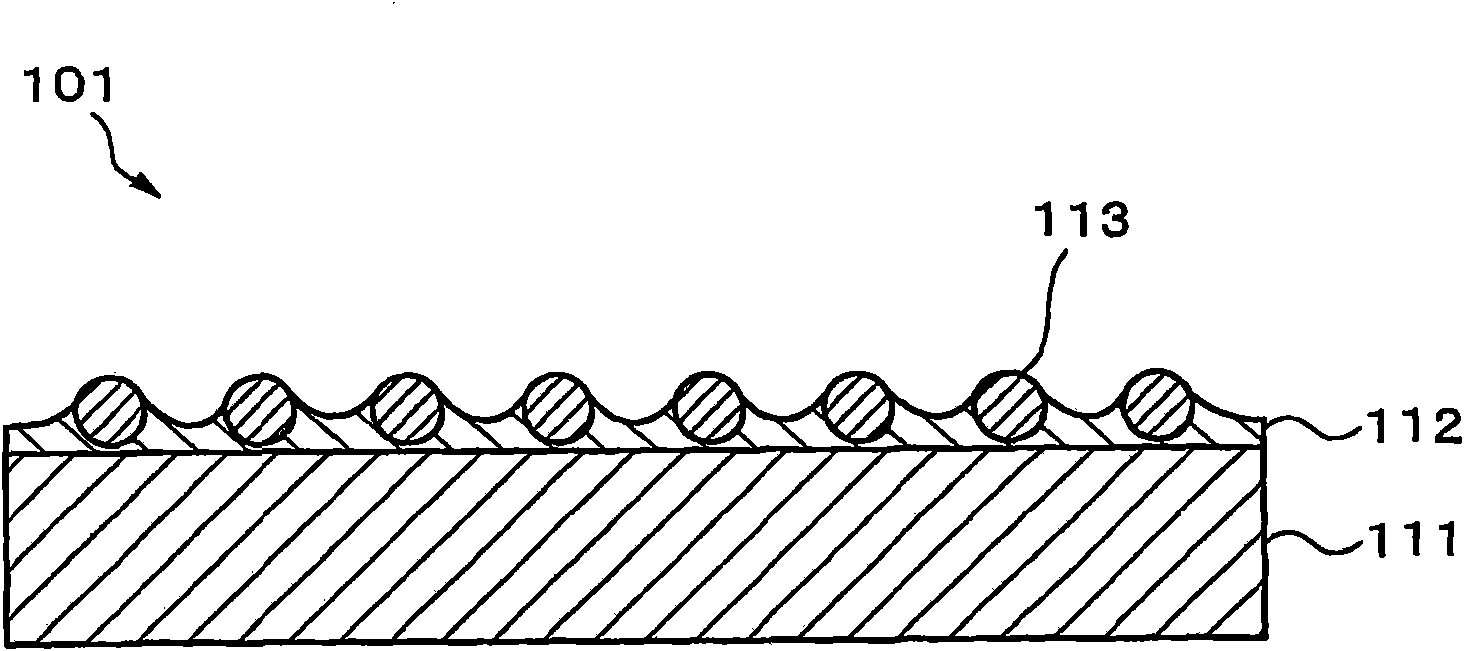
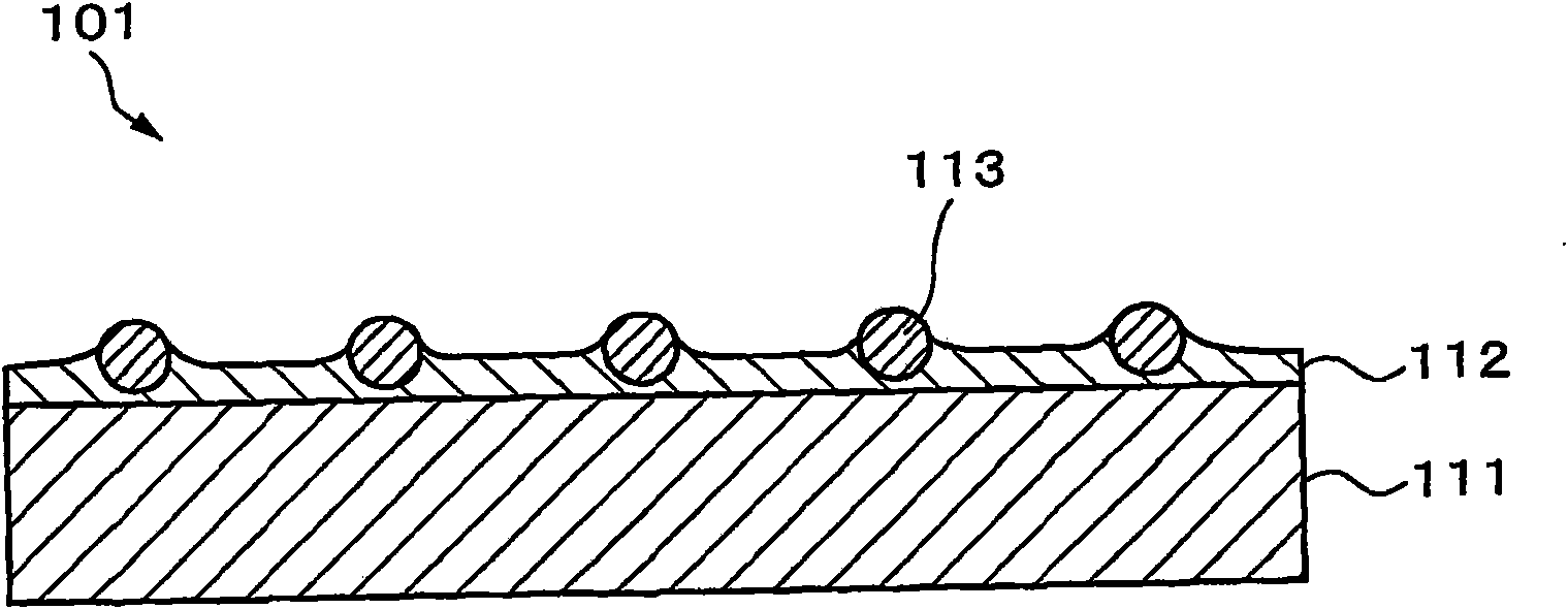
[0201] Next, a second embodiment of the present invention will be described. Although the case where the fine unevenness is formed on the surface of the anti-glare layer 12 by the fine particles 13 has been described in the foregoing first embodiment, the second embodiment will describe the formation of fine unevenness on the anti-glare layer 12 by shape transfer. The case where fine unevenness is formed on the surface.

[0202] (2-1) Structure of anti-glare film

[0203] Figure 12 One example of the structure of the antiglare film 1 according to the second embodiment of the present invention is shown. Such as Figure 12 As shown, the antiglare film 1 includes a substrate 11 and an antiglare layer 12 formed on the substrate 11 . Its structure is similar to that of the first embodiment except that the antiglare layer 12 does not include the fine particles 13 .

[0204] (2-2) Manufacturing method of anti-glare film

[0205] Next, one example of a method of manufacturing t...

no. 3 approach

[0217] (3-1) Structure of touch screen

[0218] Figure 14 is a sectional view of one example of the structure of the touch panel according to the third embodiment of the present invention. The touch screen is a resistive film type touch screen. It is set on various display devices, such as image 3 The display surface side of the illustrated liquid crystal display device constitutes a touch panel display.

[0219] The lower substrate 62 is a light-transmitting substrate such as glass. A transparent electrode film 64 is formed on the lower substrate 62 . Dot spacers 67 are formed on the transparent electrode film 64 . The insulating spacer 66 is arranged on the peripheral portion of the lower substrate 62 . The transparent film 63 is arranged to face the lower substrate 62 via the air layer 68 . The transparent film 63 becomes the surface of the touch panel that is pressed by a finger, a pen, or the like. It is a flexible film that deforms in response to pressure from a ...


PUM


Abstract

A glare-proof film (1) has a minutely irregular surface. An average interval between micro projections is 300 [mu]m or less.The derivative d{Log(I(a))}/da dependent on angle of the reflection logarithm intensity Log(I(a)) from the direction of regular reflection to the angle of deflection a has an extreme value. The derivative d{Log(P(ss))}/dss of the histogram P(ss) with respect to the angle of inclination ss of the micro projections has an extreme value. The glare-proof film (1) has a value C (2.0) of 30% or more of transmission map sharpness complying with JIS-K7105 and measured using an optical comb having a comb width of 2 mm and exhibits a ratio C (0.125)/C (2.0) of the value C (0.125) measured using an optical comb having a comb width of 0.125 mm to the value C (2.0) is 0.1 or more.

Description

technical field [0001] The present invention relates to an optical film, a method of producing such a film, an antiglare polarizer using such a film, and a display device using such a film. More specifically, the present invention relates to optical films for various display devices such as liquid crystal displays, plasma displays, rear projection displays, electroluminescence displays, CRT (cathode ray tube) displays, and touch screen displays, and to A method of producing such a film, an antiglare polarizer using such a film, and a display device using such a film. Background technique [0002] Currently, in various display devices such as liquid crystal displays, plasma displays, and CRT displays, if external light such as fluorescent lamps is reflected on the surface thereof, the visibility thereof is seriously affected. Therefore, such a method has been used to reduce reflection by forming an optical multilayer film or a low-refractive-index film on the surface of a di...

Claims


Application Information

Patent Timeline
Patent Type & Authority Applications(China)
IPC IPC(8): G02B5/02G02B5/30
CPCG02B5/0226G02B5/3025G02B5/0268G02B1/118G02B5/0278Y10T428/24479G02B5/02G02B5/30G02F1/1335
Inventor 长浜勉芳贺友美渡边仁松村伸一
Owner SONY CORP
Why Eureka
Try Eureka