
Sectional bending mould for machining heavy forging

A technology for bending processing and large forgings, which is applied in the field of segmented bending processing molds for large forgings, can solve the problems of difficulty in achieving one-time precise bending, idle general forging equipment, and thinning of the bending roots of forgings, so as to reduce abnormal bending problems and restrain The effect of side wall displacement and reduction of bending force

Inactive Publication Date: 2009-11-25
CHONGQING JIEXIN LIANZHONG MECHANICAL & MFR
View PDF0 Cites 11 Cited by
  • Summary
  • Abstract
  • Description
  • Claims
  • Application Information

AI Technical Summary

Problems solved by technology

Due to the special structure and performance indicators of large and medium-sized forgings, it is often difficult to achieve precise bending and forming with ordinary forging equipment and tooling.
If the design of the bending tooling is unreasonable, there may even be serious local thinning or even cracking quality problems at the bending root of the forging with very high requirements for various performance indicators, resulting in product scrapping
Most of the industry adopts rough bending preforming supplemented by subsequent correction procedures or purchases expensive bending machines to avoid this technical problem, which virtually increases product costs and makes existing general-purpose forging equipment idle

Method used


Image

  • Sectional bending mould for machining heavy forging
  • Sectional bending mould for machining heavy forging
  • Sectional bending mould for machining heavy forging

Examples


Embodiment Construction

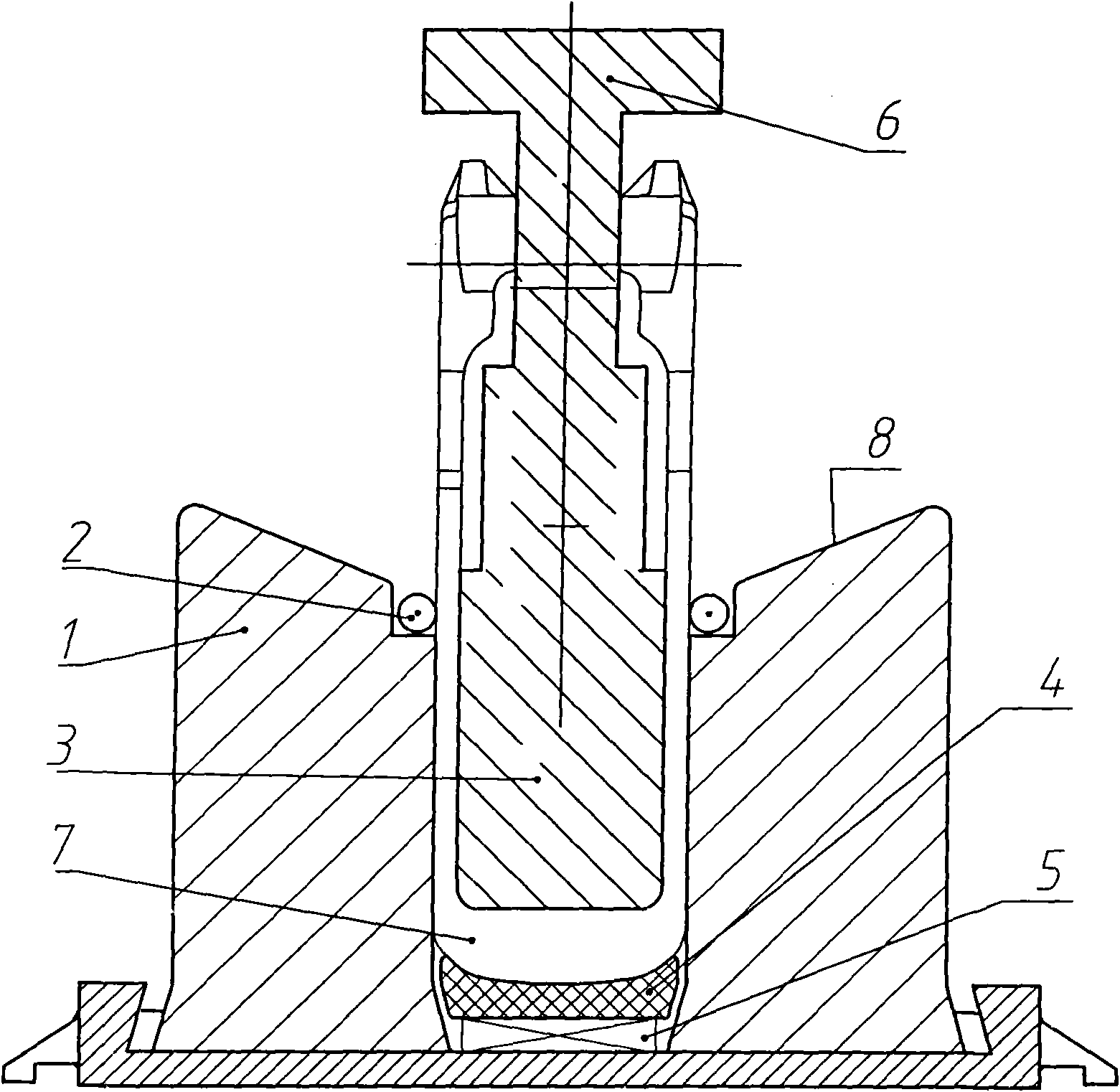
[0019] In order to illustrate the shape and structure of the present invention more clearly, the forging of the coupler frame of a railway freight car is used as an example forging below, and the present invention will be further described in detail in conjunction with the accompanying drawings.

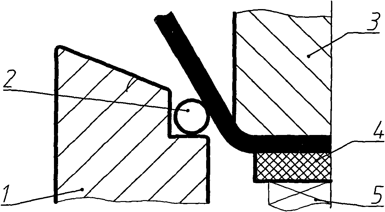
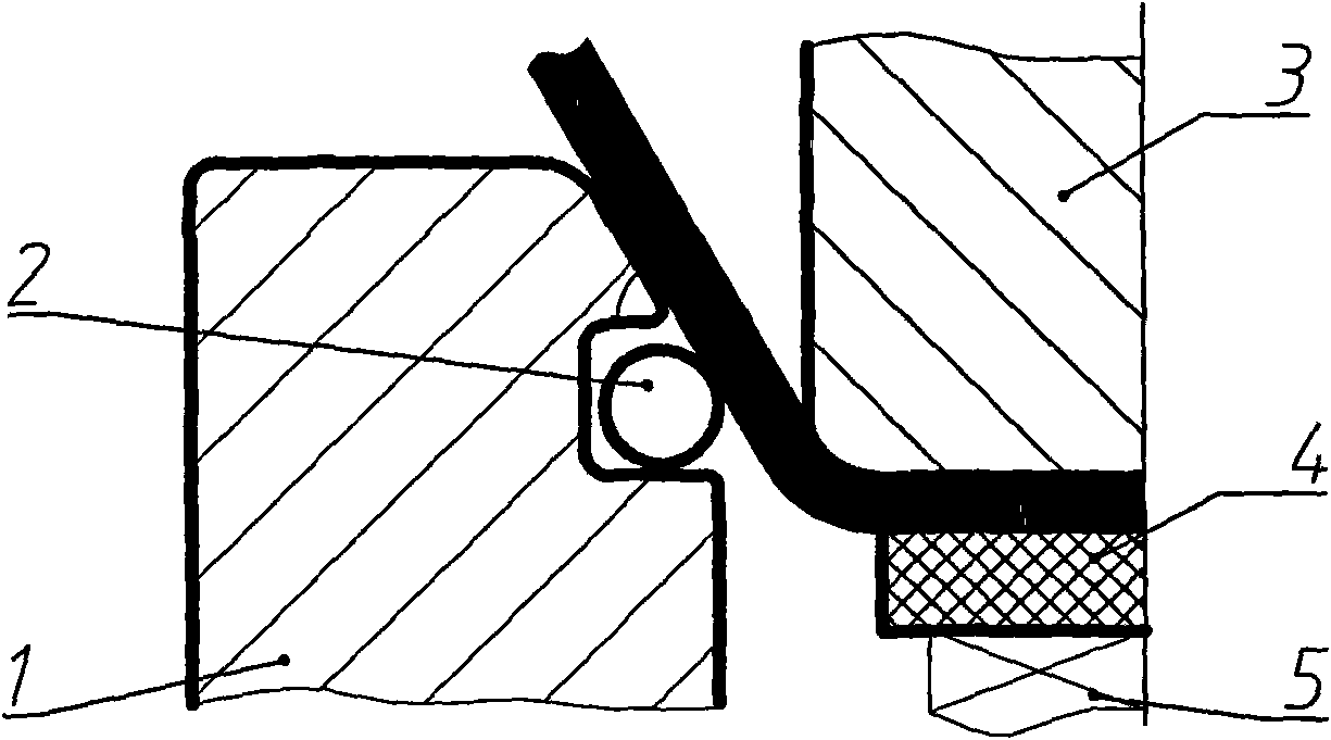
[0020] Such as figure 1 , figure 2 As shown, a segmented bending die for large forgings includes a beveled die 1, a matching punch 6 and a back pressure die 4, wherein the upper surface of the beveled die 1 has a groove cavity 7. The end surfaces on both sides of the groove cavity 7 are slopes 8 that are low inside and high outside. The highest point of the slope 8 is the fulcrum of the first bending process, and the lowest point of the slope 8 is the fulcrum of the second bending process. A roller 2 is arranged at the point, and the lower surface of the punch 6 has a boss 3 that matches the groove cavity 7, and the shape of the lower end surface of the boss 3 matches the shape of ...


PUM


Abstract

The invention discloses a sectional bending mould for machining heavy forging, includes a inclined concave mould, and a convex mould and a back pressure mould matching with the concave groove, wherein, upper surface of the inclined concave mould has a concave groove cavity with both sides end face of inner-low and outer-high inclined surface, lower surface of the convex mould has a concave plate matching with the concave groove cavity, appearance of lower surface of the convex plate is matching with shape of inner surface of middle of the forging, the back pressure mould is disposed inside the concave groove cavity with its contour of upper surface matching with shape of non-bending area of outer side of middle of the forging, the lower surface is provided with a elastic mechanism to connect with bottom of the concave groove cavity, the elastic mechanism can push the back pressure mould to upper surface of the inclined concave mould without external force. The invention can be used for machining bending of heavy forging, and has advantages of low cost and good quality.

Description

technical field [0001] The invention relates to a machining die, in particular to a segmental bending die for large forgings used for bending large forgings. Background technique [0002] The bending forming process of large forgings has always been a major problem restricting the production capacity and level of the forging industry. Due to the special structure and performance indicators of large and medium-sized forgings, it is often difficult to achieve precise bending and forming with ordinary forging equipment and tooling. If the design of the bending tool is unreasonable, there may even be serious local thinning or even cracking quality problems at the bending root of the forging that requires very high performance indicators, resulting in product scrapping. Most of the industry adopts rough bending preforming supplemented by subsequent correction process or purchases expensive special bending machine to avoid this technical problem, which virtually increases the pro...

Claims


Application Information

Patent Timeline
Patent Type & Authority Applications(China)
IPC IPC(8): B21D37/10B21D37/12B21D22/02B61G9/20
Inventor 周杰李路徐戊矫阳德森卢顺卢先正
Owner CHONGQING JIEXIN LIANZHONG MECHANICAL & MFR
Learn More