Zero energy consumption temperature reducing humidifier for bus shelter

A humidification device and zero energy consumption technology, which is applied in the field of cooling and humidification devices, can solve the problems of no ventilation and cooling measures in the waiting hall, which affects the health of waiting passengers, and achieves an effect that is conducive to environmental protection

Inactive Publication Date: 2009-11-25
HARBIN INST OF TECH
View PDF0 Cites 6 Cited by
  • Summary
  • Abstract
  • Description
  • Claims
  • Application Information

AI Technical Summary

Problems solved by technology

[0003] The purpose of the present invention is to solve the problem that the existing waiting hall has no ventilation and cooling measures, and in hot summer, the high temperature and dry waiting environment seriously affects the health of the waiting passengers, and provides a zero-energy cooling and humidifying device for the waiting booth

Method used


Image

  • Zero energy consumption temperature reducing humidifier for bus shelter
  • Zero energy consumption temperature reducing humidifier for bus shelter

Examples


specific Embodiment approach 1

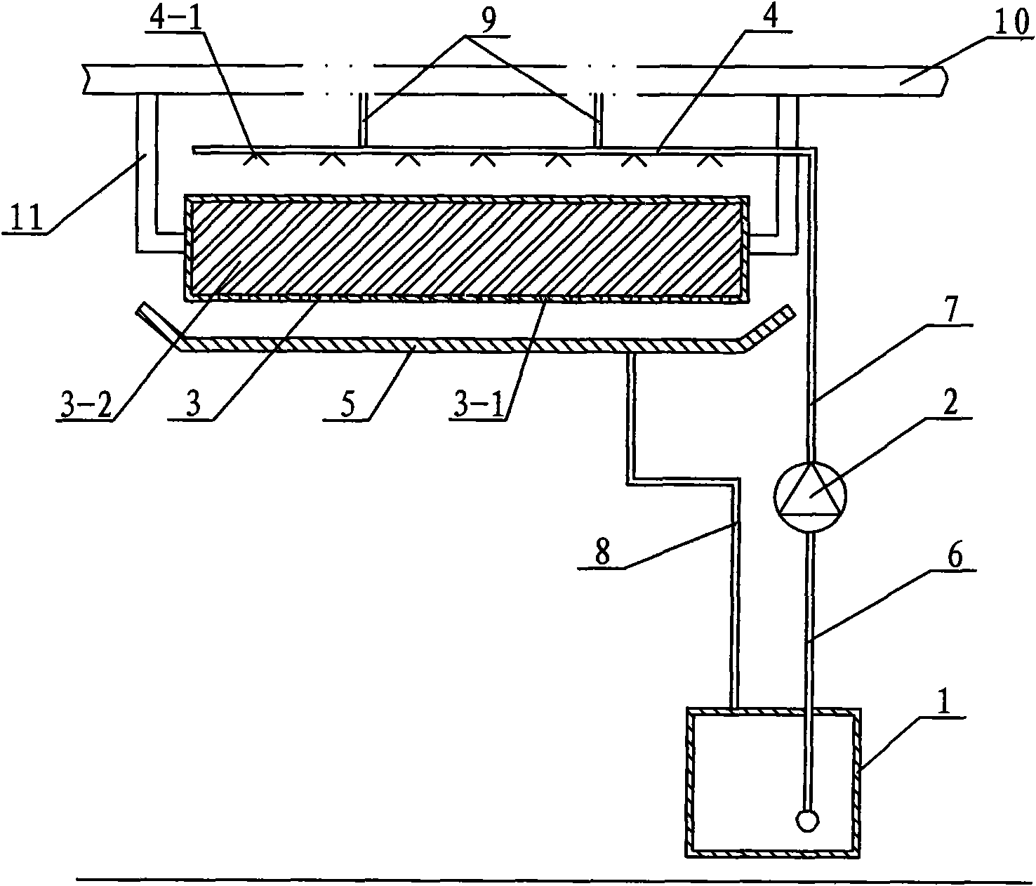
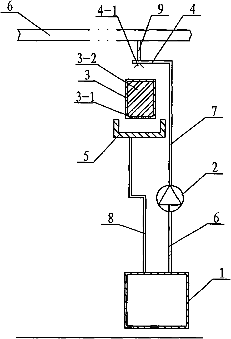
[0007] Specific implementation mode one: combine figure 1 and figure 2 This embodiment is described. This embodiment is composed of a water tank 1, a water pump 2, a stuffing box 3, a water distributor 4, a water collecting pan 5, a first pipeline 6, a second pipeline 7 and a third pipeline 8. The water tank 1 The first pipeline 6 is connected to the water inlet of the water pump 2, and the water outlet of the water pump 2 is connected to the input end of the water distributor 4 through the second pipeline 7. The stuffing box 3 is located below the water distributor 4, and the water collecting pan 5 Set below the stuffing box 3, the water outlet on the water collecting tray 5 is connected to the water tank 1 through the third pipeline 8, the stuffing box 3 is filled with hygroscopic material 3-2, and the bottom of the stuffing box 3 is provided with some water leakage holes 3 -1. Hygroscopic materials have the function of absorbing and releasing moisture, and are particular...

specific Embodiment approach 2

[0008] Specific implementation mode two: combination figure 1 The present embodiment will be described. The hygroscopic material in the stuffing box 3 of the present embodiment is paper scraps. Sawdust or paper chips can absorb or release moisture according to changes in the humidity of the surrounding environment. Other methods are the same as in the first embodiment.

[0009] Working process of the present invention: refer to figure 1 and figure 2 , the present invention runs in summer, and the roof of the bus shelter 10 is equipped with solar photovoltaic panels, and the solar photovoltaic panels are used to generate electricity to drive the water pump 2 to run, and the water pump 2 pumps the water in the water tank 1 to the water distributor 4, and then Water is sprayed onto the hygroscopic material in the stuffing box 3 through the spout 4-1 on it, and the air absorbs the heat in the air through the evaporation cooling of water in the hygroscopic material, reduces the...


PUM


Abstract

A zero energy consumption temperature reducing humidifier for bus shelter relates to a cooling device. The aim of the invention is to settle the problem that the high-temperature and dry bus waiting environment seriously affect the physical health of the waiting person in the hot summer as the prior waiting hall is not provided with a ventilating temperature-reducing facility. A water tank (1) of the invention is connected with a water pump (2) through a first pipe (6). The water pump (2) is connected with the input end of a water distributor (4) through a second pipe (7). A packing box (3) is positioned below the water distributor (4). A water collecting tray (5) is provided below the packing box (3). The water outlet on the water collecting tray (5) is connected with a water tank (1) through a third pipe (8). The hygroscopic material (3-2) is filled in the packing box (3). The bottom of the packing box (3) is provided with a plurality of water leaking openings (3-1). The invention uses the hygroscopic material for reducing the temperature in the waiting hall and creating a comfortable bus waiting environment for the bus shelter. The low-temperature and humid bus waiting environment is good for the physical health of the waiting person.

Description

technical field [0001] The invention relates to a cooling and humidifying device. Background technique [0002] Existing waiting hall is open, without ventilation and cooling measures, in hot summer, the temperature is very high, high temperature and dry waiting environment seriously affects the health of waiting passengers. Contents of the invention [0003] The purpose of the present invention is to solve the problem that the existing waiting hall has no ventilation and cooling measures, and in hot summer, the high temperature and dry waiting environment seriously affects the health of the waiting passengers, and provides a zero-energy cooling and humidifying device for the waiting booth . [0004] The present invention is composed of a water tank, a water pump, a stuffing box, a water distributor, a water collecting tray, a first pipeline, a second pipeline and a third pipeline. The water tank is connected to the water inlet of the water pump through the first pipeline...

Claims


Application Information

Patent Timeline
Patent Type & Authority Applications(China)
IPC IPC(8): F24F6/00F24F6/04
Inventor 倪龙江辉民陈超姚杨姜益强马最良
Owner HARBIN INST OF TECH
Why Eureka
Try Eureka