Soft insulating optical fiber insulator

An insulator and software technology, applied in the coupling of optical waveguides, etc., can solve the problems of short service life, complex processing, large optical loss, etc., and achieve the effect of improving insulation performance and service life, simplifying processing technology, and reducing optical loss.

Inactive Publication Date: 2009-11-25
HARBIN INST OF TECH +1
View PDF0 Cites 14 Cited by
  • Summary
  • Abstract
  • Description
  • Claims
  • Application Information

AI Technical Summary

Problems solved by technology

[0005] The purpose of the present invention is to solve the problems of poor insulation performance, large optical loss, complicated processing, low yield and short service life of existing optical fiber insulators, and further provide a soft insulated optical fiber insulator

Method used


Image

  • Soft insulating optical fiber insulator
  • Soft insulating optical fiber insulator
  • Soft insulating optical fiber insulator

Examples


specific Embodiment approach 1

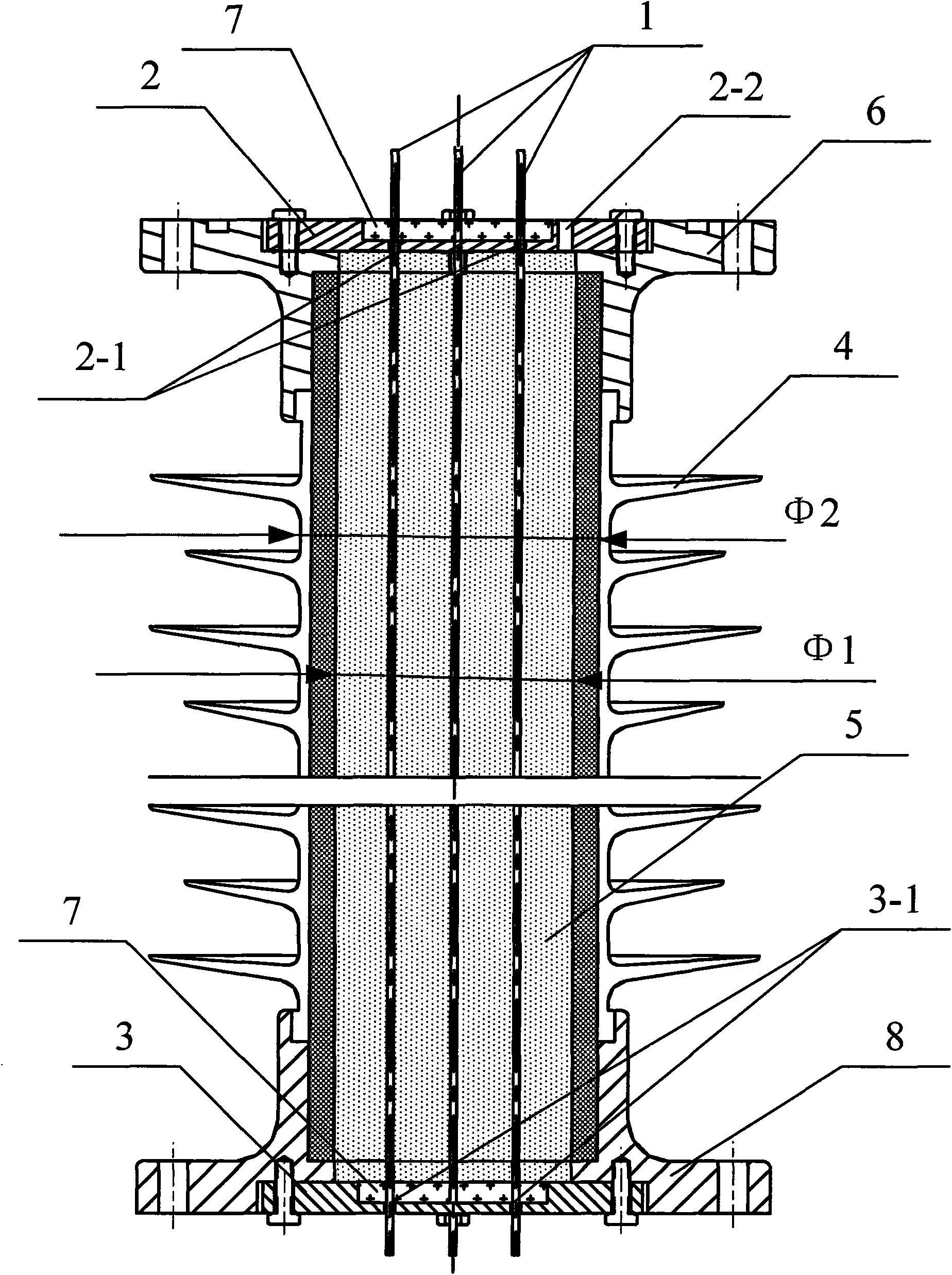
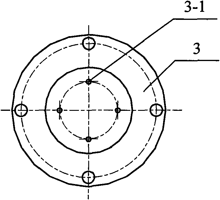
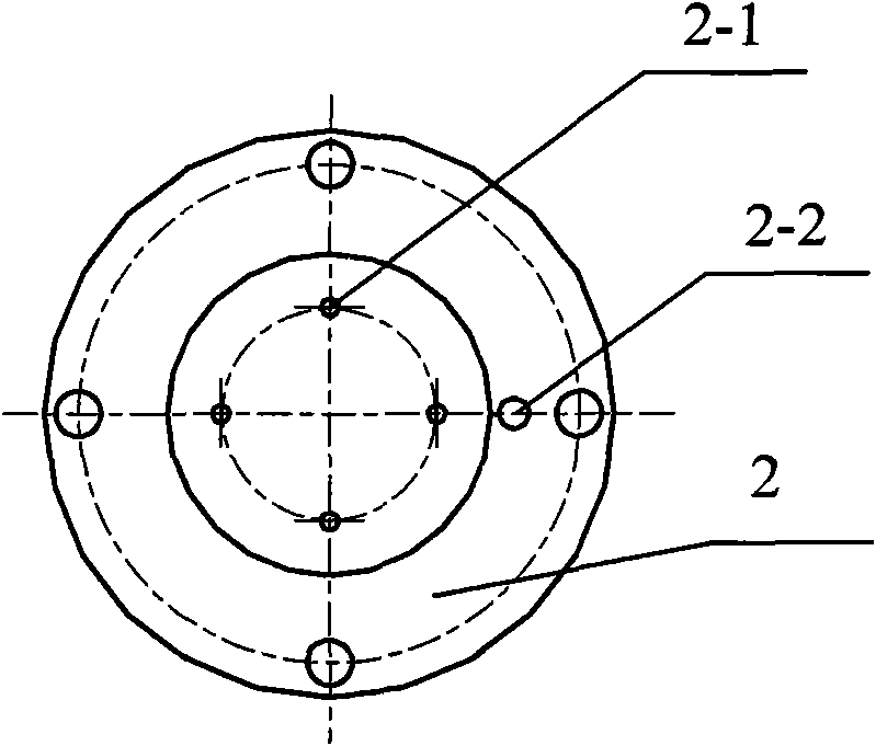
[0009] Specific implementation mode one: combine Figure 1 ~ Figure 3 Describe this embodiment, the soft insulated optical fiber insulator of this embodiment consists of multiple optical fiber jumpers 1, an upper metal end cap 2, a lower metal end cap 3, an upper metal flange 6, a lower metal flange 8, a hollow insulator 4, a software Glue 5 and two layers of sealant 7, the upper end of the hollow insulator 4 is fixed to the upper metal end cover 2 through the upper metal flange 6, and the lower end of the hollow insulator 4 is connected to the lower metal end cover through the lower metal flange 8 3 fixed connection, the upper metal end cover 2 has a plurality of through holes 2-1 and a glue injection hole 2-2, the lower metal end cover 3 has a plurality of through holes 3-1, and the upper The plurality of through holes 2-1 on the metal end cover 2 correspond to the plurality of through holes 3-1 on the lower metal end cover 3, and the plurality of optical fiber jumpers 1 pen...

specific Embodiment approach 2

[0010] Specific implementation mode two: combination figure 1 The present embodiment will be described. The hollow insulator 4 of the present embodiment is a hollow composite insulator with a silicone rubber outer insulation. Other compositions and connections are the same as in the first embodiment.

specific Embodiment approach 3

[0011] Specific implementation mode three: combination figure 1 The present embodiment will be described. The ratio of the inner diameter φ1 to the outer diameter φ2 of the hollow composite insulator with silicone rubber outer insulation in this embodiment is ≤0.66. In this way, the flexural and compressive modulus of the hollow composite insulator with silicone rubber outer insulation is greater than that of the solid state, which meets the mechanical performance requirements of the hollow composite insulator with silicone rubber outer insulation. During the implementation of the process, the inner wall of the hollow composite insulator with the outer insulation of silicone rubber is machined once to ensure its smoothness. Other compositions and connections are the same as those in the second embodiment.


PUM


Abstract

A soft insulating optical fiber insulator relates to an insulating optical fiber insulator. The soft insulating optical fiber insulator of the invention settles the problems of inferior insulating property, large optical loss, complex processing, low finished product rate and short service lifetime existing in the prior optical fiber insulator. The upper end of the hollow insulator of the invention is fixedly connected with an upper metal end cap through the upper metal flange. The lower end of the hollow insulator is fixedly connected with the lower metal end cap through a lower metal flange. The upper metal end cap is provided with a plurality of through holes and one glue injection hole. The lower metal end cap is provided with a plurality of through holes. A plurality of optical fiber jumper wires run through the inner chamber of the hollow insulator. The interfaces between the plurality of optical fiber jumper wires and the upper metal end cap and the lower metal end cap are respectively provided with one layer of sealant. The soft glue is injected into the inner chamber of the hollow insulator through a glue injection opening on the upper metal end cap. The soft insulating optical fiber insulator of the invention has the advantages of increasing the insulating property and service lifetime of the optical fiber insulator, greatly reducing the optical loss, simplifying the processing technique and increasing the finished product rate of the product.

Description

technical field [0001] The invention relates to an insulating optical fiber insulator. Background technique [0002] Insulated fiber optic insulators are suitable for electronic current transformers that measure current in high-voltage and ultra-high voltages in power systems. They are used as high-voltage insulation and support for high-voltage components of electronic current transformers, and transmit optical signals from high-voltage terminals to low-voltage terminals. At present, optical fiber insulators are generally optical fiber composite insulators with silicone rubber outer insulation. Use a solid epoxy rod, slot the wall of the epoxy rod, bury the optical fiber, then use silicone rubber, epoxy resin or other similar organic materials to bond and seal, and then set the outer surface of the epoxy rod to meet the requirements of external insulation. Umbrella sheath; or a hollow composite insulator is used, the optical fiber is passed through the through hole of the ...

Claims


Application Information

Patent Timeline
Patent Type & Authority Applications(China)
IPC IPC(8): G02B6/38
Inventor 郭志忠张国庆于文斌申岩路忠峰孙如京王贵忠
Owner HARBIN INST OF TECH
Why Eureka
Try Eureka