
Method and device for realizing demodulation of mixing auger phase light beam orbit angular momentum state
An orbital angular momentum and hybrid spiral technology, which is used in measurement devices, light demodulation, interferometric spectroscopy, etc. Orbital Angular Momentum, etc.
- Summary
- Abstract
- Description
- Claims
- Application Information
AI Technical Summary
Problems solved by technology
Method used
Image


Examples
Embodiment Construction
[0025] The specific embodiments of the present invention will be further described below in conjunction with the accompanying drawings.
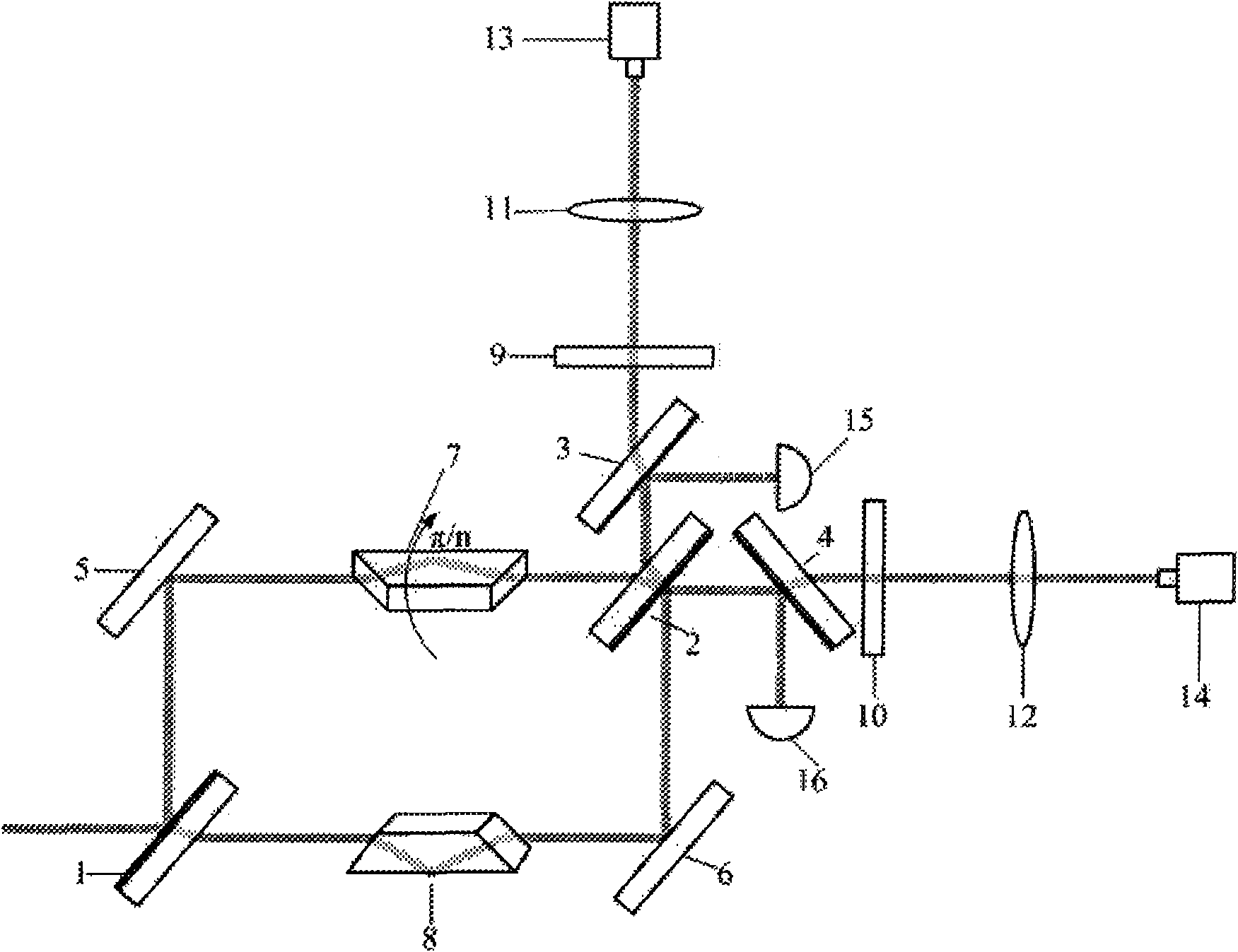
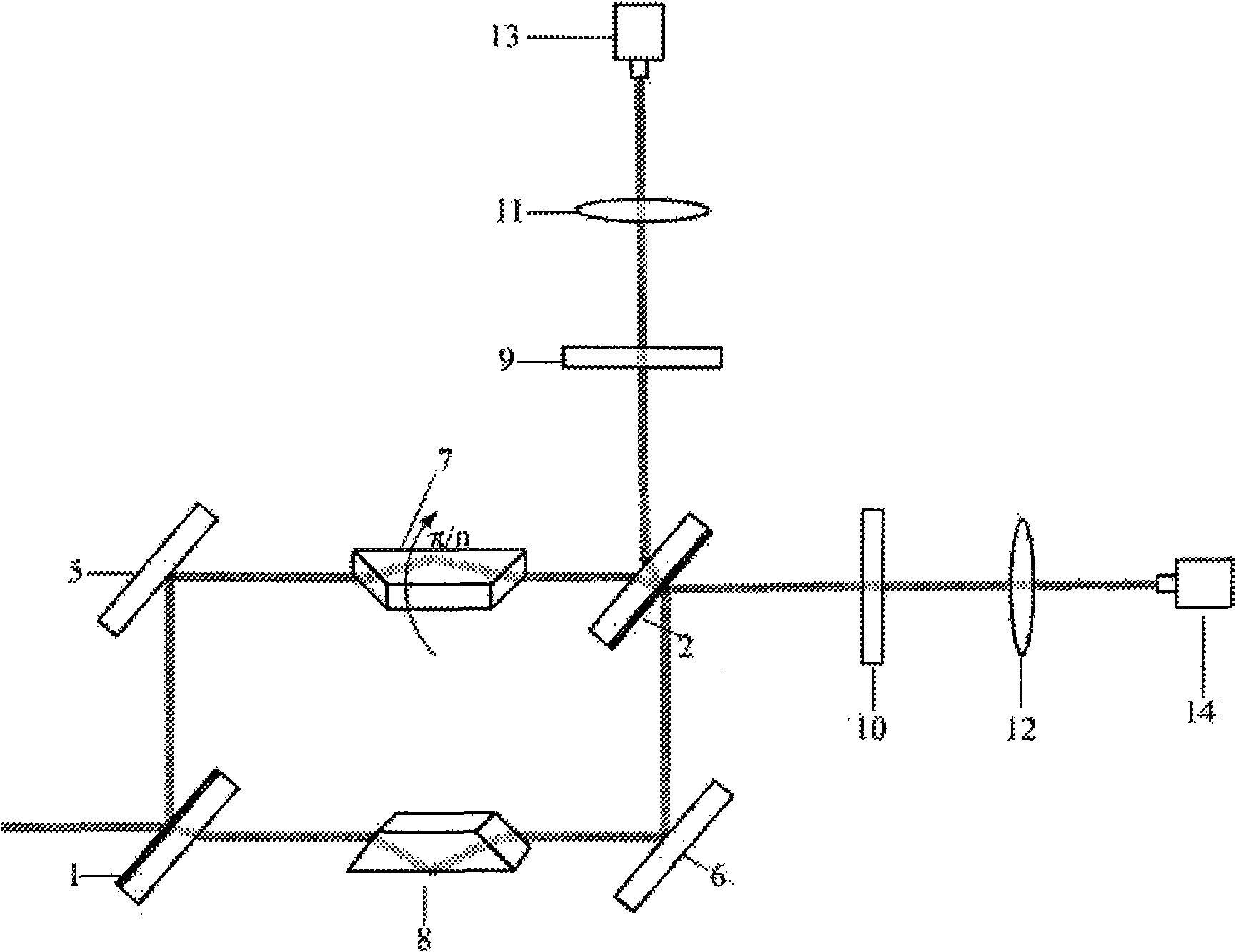
[0026] Such as figure 1 As shown, the device of the present invention includes beam splitters 1, 2, 3, 4, total reflection mirrors 5, 6, Dove prisms 7, 8, diffraction gratings 9, 10, convex lenses 11, 12, CCD detectors 13, 14, energy Count 15, 16. The energy splitting ratio of beam splitters 1, 2, 3, and 4 is 50 / 50. The beam splitting film of beam splitter 1 is located on the front surface of the incident light, forming an angle of 45° with the incident light. The mirrors 1 are parallel to each other, the beam splitters 3 and 4 are respectively located at the two output ends of the Mach-Zehnder interferometer and are perpendicular to each other, the beam splitter 3 and the beam splitter 1 are parallel to each other; the total reflection mirrors 5 and 6 are 45° total reflections, and the reflection The planes are all parallel to the beam sp...
PUM
 Abstract
Description
Claims
Application Information