Armrest apparatus

A technology of handrails and rolls, which is applied in the directions of handrails, transportation and packaging, special positions of vehicles, etc., can solve problems such as troublesome operation, and achieve the effects of easy production, size reduction and weight reduction.

Inactive Publication Date: 2009-12-02
BIZEN HATSUJO
View PDF3 Cites 10 Cited by
  • Summary
  • Abstract
  • Description
  • Claims
  • Application Information

AI Technical Summary

Problems solved by technology

Therefore, when the angle is changed downward, pull up the armrest once it exceeds the adjustment range, release the locked state through the release mechanism, then pull it down to the lower limit position, reset it through the recovery mechanism, and then pull it up to the desired position. The troublesome operation of the angle is forced to
In addition, if this operation fails, it is necessary to perform a very troublesome operation in which the same operation is performed again

Method used


Image

  • Armrest apparatus
  • Armrest apparatus
  • Armrest apparatus

Examples


Embodiment Construction

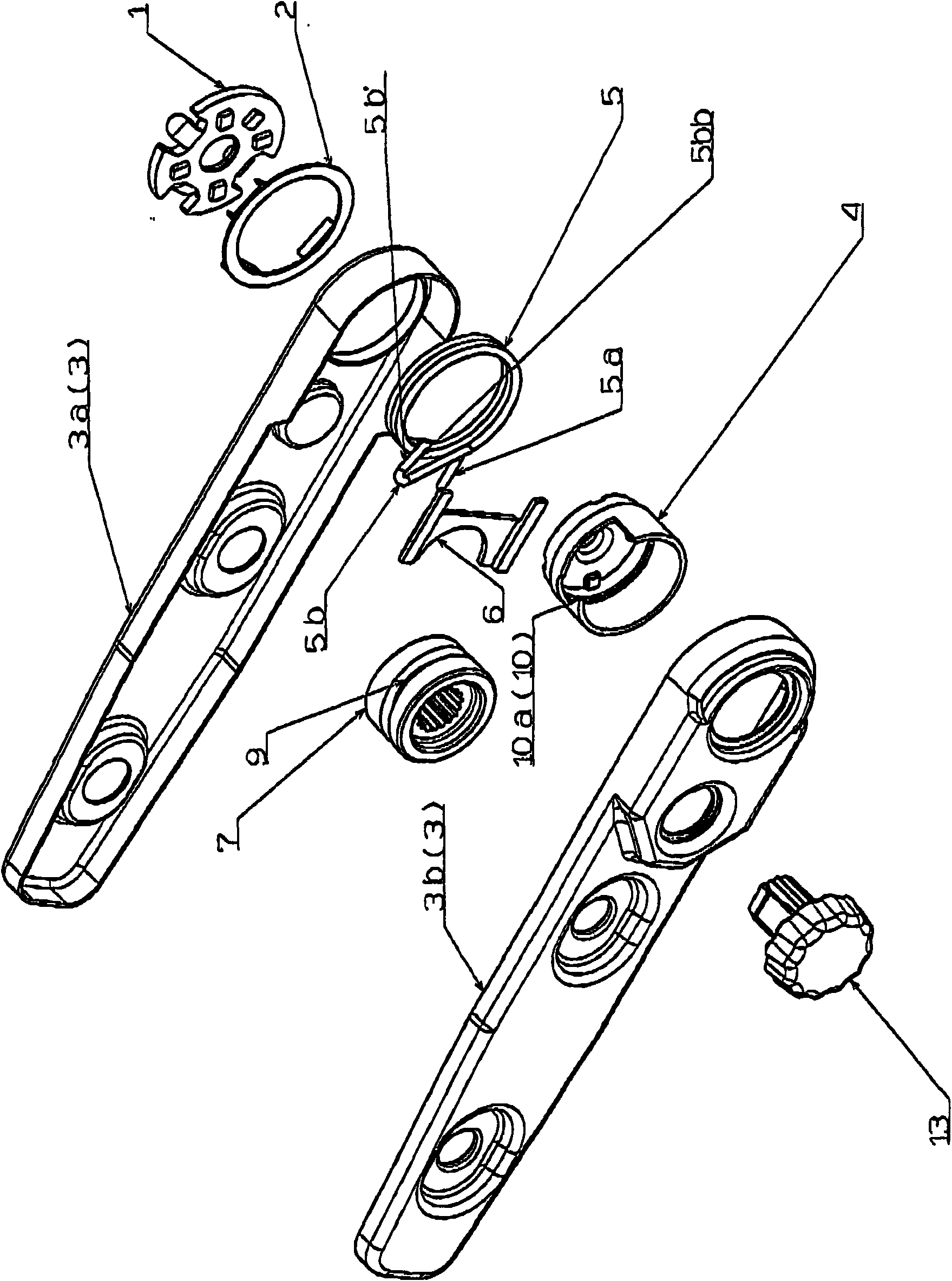
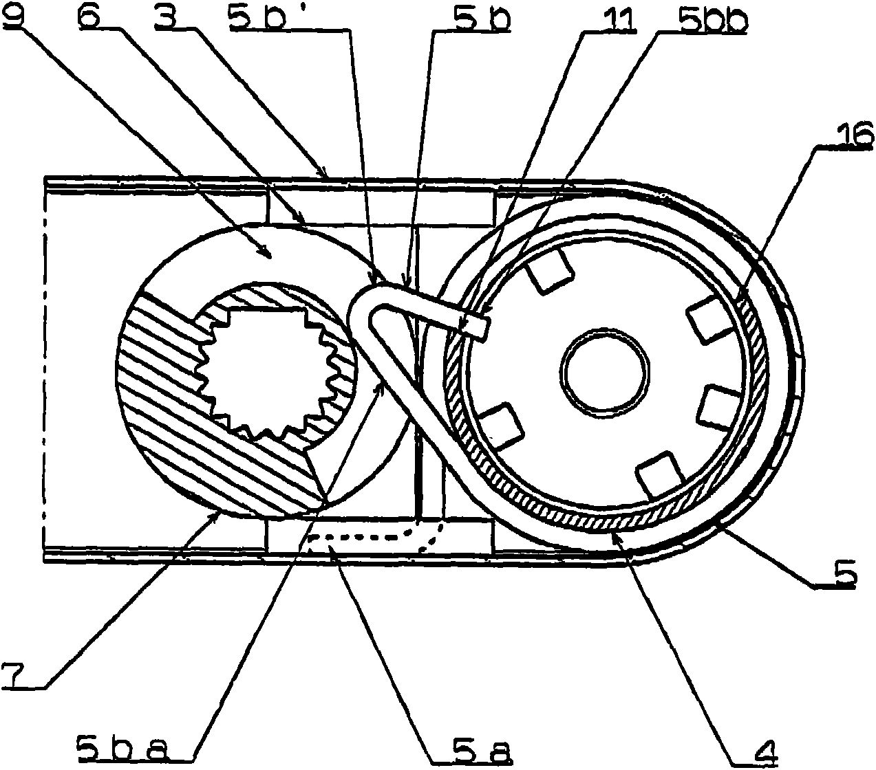
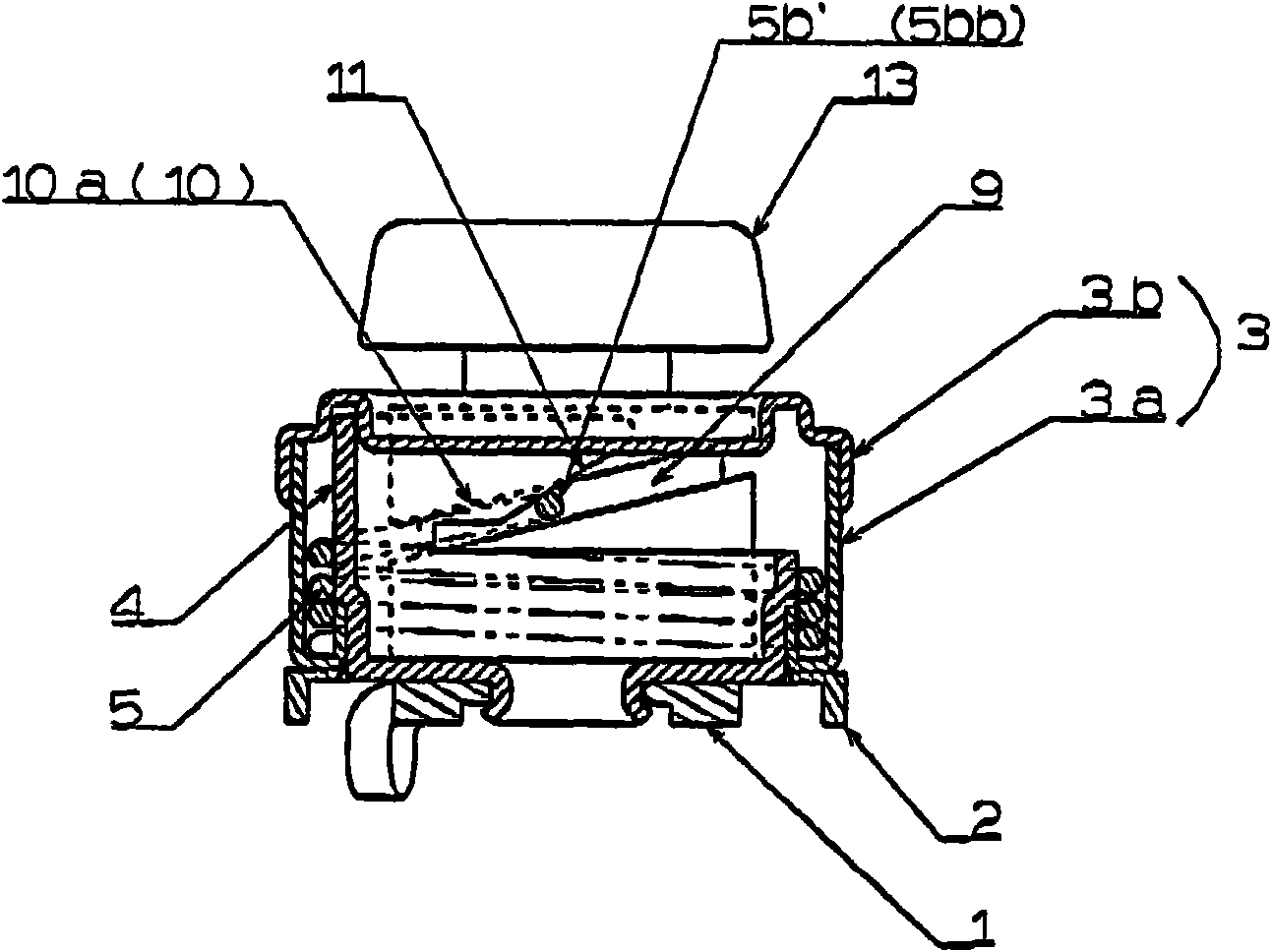
[0018] Embodiments of the present invention will be described below with reference to the drawings. figure 1 It is an exploded perspective view of the armrest device of the present invention, figure 2 is a longitudinal sectional view of the main part, image 3 is a transverse sectional view of the main part, Figure 4 It is an expanded view of a part of the reel with the support surface formed on the reel side, and the armrest device is composed of a mounting piece 1, a washer 2, a combined half arm 3a, a reel 4, a coil spring 5, a housing 3b, a reinforcing body 6, and an operating part 7 and operation button 13, etc., the mounting part 1 is fixed on the seat frame from the side of the seat frame (not shown), the combined half arm 3a constitutes the arm 3, and the reel 4 is fixed to the mounting part 1 through the washer 2 In this coil spring 5, one end is fixed on the combined half-arm 3a to form a fixed end 5a, and the other end forms a free end 5b, which is moved along t...


PUM


Abstract

An armrest apparatus including an arm, which is fitted to a drum provided on a seat side member, and a coil spring, which is provided on the drum, wherein one end of the spring is fixed to the arm-rest member and another end of the spring, a free end, is curved outwardly in the direction away from the center axis of the drum, and this coil spring is loosely wound around the drum so as to tighten when the arm-rest member is rotated downward, and further a coil end receiving surface that receives the curved part of the coil spring is provided in the drum. When the arm-rest member is rotated downward and reaches a predetermined set angle, the coil end receiving surface receives the curved part of the coil spring, so that the coil spring tightens the drum by a downward load applied to the arm, restricting the downward rotation of the arm.

Description

technical field [0001] The present invention relates to an armrest device provided on various seat seats including automobile seats. Background technique [0002] There is a mechanism generally called a spring lock, in which the inner diameter of the coil spring wound on the fixed shaft is smaller than the outer diameter of the shaft, and if it is in a tightened state at ordinary times, the coil spring can be moved in the direction of rewinding (loosening) direction) to rotate freely, however, in the winding direction (tightening direction), the coil spring fastens the shaft and restricts its rotation through its frictional resistance. This mechanism is of the type used for, for example, an armrest of a car (Patent Document 1). According to this mechanism, although it has the advantage of simple structure, in normal times, the locking force depends on the frictional resistance corresponding to the fastening force of the coil spring wound in the state fastened to the shaft, ...

Claims


Application Information

Patent Timeline
Patent Type & Authority Applications(China)
IPC IPC(8): A47C1/03A47C7/54B60N2/46B60N2/75
CPCB60N2/4633B60N2/767
Inventor 山根孟士小林德三冈本昭彦田村健吾
Owner BIZEN HATSUJO
Why Eureka
Try Eureka